2 - Install & Maintenance Guides
Guides, Instructions and Tutorials
- MikroTik Netinstall Recovery
- Chromebook Developer Mode (Getting a terminal)
- Crimping
- DIY Install Overview
- Equipment
- Etiquette
- Link NYC Kiosk (Kiosk Node)
- Juniper Quick Start Guide (Mikrotik vs Juniper)
- Post Install (New Member Form)
- Common Issues and How to Avoid Them
- Query
- Safety
- Typical Install Diagram (Omni & Litebeam)
- Typical Install Diagram (Omni-only)
- Typical Installs
- Siklu Alignment
- Ubiquiti Unifi AP Adoption Guide (WORK IN PROGRESS)
- Omni PoE Diagram
- Fiber Optics
- Fiber Safety
- Nyc Mesh Fiber Background And Splicing Guide
- Fiber Splicing Tutorial
- Fiber to the Apartment
- Fiber install guidelines
- Physical Installation
- Install Planning and Surveys
MikroTik Netinstall Recovery
How to resurrect a bootlooping OmniTIK with netinstall
Symptoms
OmniTIK boots up but continually reboots. The LEDs repeat the pattern: device boots up, power eventually turns blue, then 1-5 turn orange and reboots. Rinse and repeat.
Solution
Use netinstall to flash a fresh firmware on the router. This guide assumes Linux, though both Linux and Windows are supported. This should work for any RouterBOARD based device.
- Install
netinstallon your laptop from mikrotik, and make sure it is in your command line path - Download the firmware you want to reset to (e.g.
routeros-mipsbe-6.47.8.npk) - Plug the data end of PoE injector into your computer's ethernet (e.g.
enp0s13f0u2u4u5) - Press and hold the reset button on the omnitik
- Plug the poe+data end into ether1 of omnitik
- Keep holding the reset button until LED 1 is solid orange, and the blue light has stopped flashing and is now off
- Finally, run
netinstalland reset the board:
❱ netinstall -p ~/Downloads/routeros-mipsbe-6.47.8.npk -i enp0s13f0u2u4u5
Using server IP: 192.168.88.2
Starting PXE server
Waiting for RouterBOARD...
PXE client: CC:2D:E0:17:55:CB
Sending image: mips
Discovered RouterBOARD...
Formatting...
Sending package routeros-mipsbe-6.47.8.npk ...
Ready for reboot...
Sent reboot command
After all this, you should hear a few beeps indicating success. You can now try to connect via ether2 to configure it at 192.168.88.1 as normal.
Chromebook Developer Mode (Getting a terminal)
Chromebooks are good for installs as they are cheap and all you need is a browser and a terminal anyway.
To get a standard terminal you have to put the Chromebook in developer mode:
This will erase your login info and any local data!
-
Turn the Chromebook off
-
Turn it on while holding esc and ⟳ (escape and reload)
-
Wait for the next screen that says something like "Chrome OS is missing or..."
-
Press Ctrl-D
-
Wait for next screen
-
Press enter
The Chromebook should restart and you can sign is as guest or enter your gmail etc to set up the laptop.
-
ctrl-T to get a terminal
-
type
shellat the prompt to get a standard shell
The next time you start your Chromebook-
- Press Ctrl-D to continue (don't press the spacebar!)
Crimping
Here are some helpful videos on crimping. Like nearly everyone we use the T-568B standard
Video 1
Video 2
DIY Install Overview
For a DIY ("do it yourself") install we recommend joining our Slack group where you can chat with us.
There is a channel in Slack- #diy-install-support where you can ask questions. We can guide you on what hardware to buy, and what is likely the best connection to a nearby antenna.
For DIY, you must still fill in our join form. This will give you an Install Number (or request number) which you will need when you are ready for an install to request a Network Number (or NN) in order to be able to configure your devices for your install. It will also get you in our system so we can give you advice and look for line-of-sight connections, as well as put you on the map. (We are working at automating the process so you can use the Install Request number and the system will automatically allocate a Network Number for you. For now you need to request it via #diy-install-support or via the email your received with your Request Install Number)
For a quick check of line-of-sight you can use our line-of-sight tool. Put in your address and it will show you which hubs you might be able to connect to.
Here is a list of equipment we typically use. Remember to use outdoor ethernet cable, and securely mount your antennas on j-pipes or secured masts. Masts should be strong metal as plastic PVC pipes will bend.
Our general install advice is here in the docs
When you are ready, here's how to configure your devices.
We ask you, if you can, to support NYC Mesh with a monthly subscription. Donating helps maintain, operate, and expand NYC Mesh so, just like you, others can benefit from the network.
Equipment
To connect to NYC Mesh, you will need to install wireless networking equipment on a rooftop or outside a window. This page lists a range of equipment and tools that are commonly used for typical installations. Before assembling any equipment, first carry out a site survey and make an install plan to narrow down the equipment you really need. For detailed information about specific routers, visit the hardware docs.
You can download a handy checklist of the equipment listed on this page here.
For DIY installers: To get help figuring out which essential equipment you need for your installation, first familiarize yourself with the equipment below and then reach out to the NYC Mesh community on slack on the #diy-install-support channel.
For volunteer installers: Prior to any install, make sure you have access to the equipment listed below. If you are missing any equipment needed for an install, reach out to install leaders on slack on the #install-team channel to ask to borrow them. Shared tools are available and we can purchase, order and ship networking equipment (routers, cable, connectors, etc.) to your address.
Networking Equipment
| Product Name | Product Photo | What it's used for | Where you can get it | Cost |
|---|---|---|---|---|
| Laptop (charged) |  |
Configuring outdoor and indoor routers, reading docs and install plan | Bring your own | |
| Outdoor router(s) (pre-configured) |  |
Connecting to a node | Order online or collect from mesh room stock (refer to specific product page in hardware docs) | |
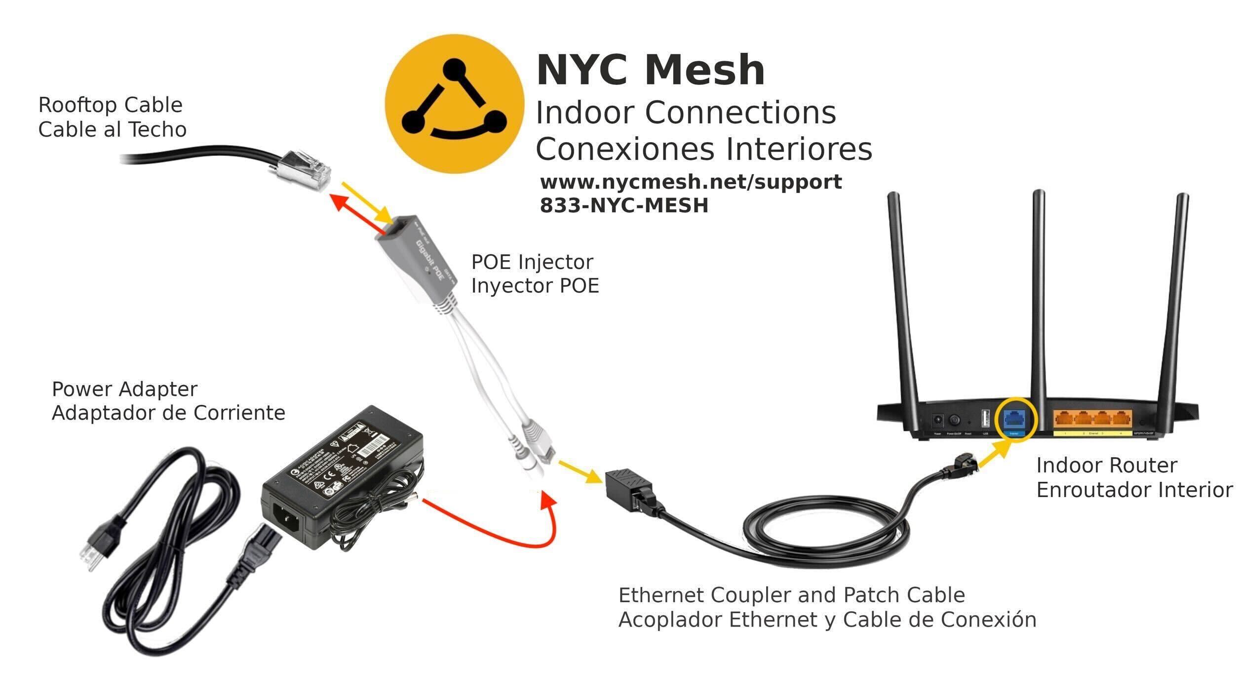
| Power Over Ethernet (POE) adapter and power cable |  |
Providing power to the outdoor router and passing data to and from indoor router | Comes packaged with the outdoor router | |
| Indoor router |  |
Connection point for user's devices | Order online or collect from mesh room stock | $20+ |
| CAT5e cable (outdoor-rated, grounded and shielded) |  |
Passing power and data between outdoor router, indoor router and power outlet | Available from online retailers in different spool lengths - recommended product | $130-150/1000ft $90-110/500ft $20-30/100 ft |
| RJ45 pass through connectors (metal, with grounding loop) |  |
Gets crimped onto the ends of the CAT5e cable to provide power and data interface | Available from online retailers - recommended product | $0.34/connector |
| Two Ethernet patch cables |  |
Connecting routers to POE injector, battery pack, laptop | Available from online retailers - recommended product | $1.5-2 per <=3ft cable |
| Portable battery pack with three-prong power outlet (charged) |  |
Providing power to outdoor router while surveying for signal | Available from online retailers - recommended product (less expensive) / recommended product (better features) | $50 for 11,600 mAh $150 for 46,400 mAh |
| Gigabit USB/Thunderbolt to Ethernet adapter |  |
Connecting laptop without an ethernet port to outdoor router (not needed if connecting wirelessly) | Available from online retailers | $15 |
Tools
| Product Name | Product Photo | What it's used for | Where you can get it | Cost |
|---|---|---|---|---|
| Ethernet cable crimper (pass through) |  |
Attaching RJ-45 connectors to CAT5e cable | Online retailers - recommended product | $44 |
| CAT5e cable stripper |  |
Stripping CAT5e cable | Online retailers (included in crimping all-in-one kit) - recommended product | $25 for crimping all-in-one kit |
| Ethernet cable tester |  |
Testing that Ethernet cable has been correctly crimped | Online retailers - recommended product | $10 |
| Spare 9v battery |  |
Replacement in case tester is left on | Online retailers - recommended product | $10 |
| Scissors |  |
Cutting CAT5e cable and cable ties | Hardware store tools aisle | |
| Needlenose pliers |  |
Clamping CAT5e cable ground wire, pulling cable through holes | Hardware store tools aisle - recommended product | $12 |
| Cordless hammer drill |  |
Drilling holes, inserting screws, securing pipe clamps | Hardware store tools aisle | |
| Hex socket drill bits (3/8" for hose clamps and 1/4" for masonry screws) |  |
Tightening hose clamps, inserting concrete screws | Hardware store drill bits aisle | |
| Carbide-tip masonry drill bit (5/32") |  |
Drilling holes in concrete or masonry for inserting masonry screws | Hardware store drill bits aisle | |
| Cobalt / titanium drill bit (1/4") |  |
Drilling hole for CAT5e cable to pass through steel window frame | Hardware store drill bits aisle | |
| Hammer |  |
Driving in concrete nails | Hardware store tools aisle | |
| Concrete nail |  |
Starting a hole in concrete or masonry (makes drilling easier) | Hardware store nails aisle | |
| Phillips Precision Screwdriver (No. 1) |  |
Assembling Litebeam Router | Included in crimping all-in-one kit, Hardware store tools aisle | |
| Adjustable crescent wrench (6") |  |
Assembling J-pipe mount | Hardware store tools aisle | |
| Vise grips |  |
Removing stuck drill bits | Hardware store tools aisle |
Mounting Equipment
| Product Name | Product Photo | Field Photo | What it's used for | Where you can get it | Cost |
|---|---|---|---|---|---|
| Small diameter (28) hose clamp |  |
 |
Securing the router to a thin mast or pipe | Comes with outdoor router, hardware store plumbing aisle | |
| Large diameter (88) hose clamp |  |
 |
Securing the router or mast to a large pipe or window guard | Hardware store plumbing aisle | |
| J pipe antenna mast |  |
 |
Mounting to a wall or parapet | Online retailers - recommended product / 10-pack | |
| L pipe antenna mast |  |
 |
Orienting an SXT router up and down | Online retailers - recommended product | |
| Concrete screws (3/16" hex head CSH316134) |  |
 |
Securing mast mounts to concrete or masonry | Hardware store screws and anchors aisle | |
| Washers (1/4" hole diameter) |  |
|
Securing mast mounts to concrete or masonry | Hardware store fasteners aisle | |
| Zip ties |  |
 |
Securing ethernet cable | Hardware store electrical aisle | |
| Cable staples |  |
 |
Securing ethernet cable to an indoor wall | Hardware store electrical aisle | |
| Cable fastener clips |  |
|
Securing ethernet cable to an outdoor vertical surface | Hardware store electrical aisle or online retailers - recommended product |
Miscellanious supplies
| Product Name | Product Photo | What it's used for | Where you can get it |
|---|---|---|---|
| Electrical tape |  |
Pulling cable through holes | Hardware store adhesives aisle |
| Weather stripping (9/16" thick or greater) |  |
Sealing the bottom of a window when the CAT5e cable is run over the window frame | Hardware store insulation aisle |
| Rubberized waterproof sealant |  |
Sealing gaps and holes to prevent water infiltration | Hardware store adhesives aisle |
| WD-40 or other oil |  |
Drilling through thicker metals | Hardware store |
| Small brush and dustpan |  |
Sweeping up cable ends and metal shavings from drilling through window frame | Online retailers |
| Biodegradable wet wipes |  |
Cleaning dirty hands | Online retailers - recommended product |
| Small garbage bag |  |
Disposing of garbage | Reuse a shopping bag |
| Hand truck |  |
Transporting cable reel box and equipment bag in and out of subway stations - stair-climbing model is ideal! | Online retailers, larger hardware stores |
| Backpack |  |
Transporting equipment safely up ladders - slim backpacks are the safest! | Many places |
Safety gear
| Product Name | Product Photo | What it's used for | Where you can get it |
|---|---|---|---|
| Safety Glasses |  |
Eye protection while drilling | Hardware store apparel aisle |
| Thick-soled shoes or work boots |  |
Protection against sharp objects on rooftops | Work wear store |
| Sunblock and hat (in summer) |  |
Preventing sunburn | Pharmacy |
| Cold weather apparel (in winter) |  |
Preventing frostbite | Clothing store |
| Water and a snack |  |
Staying hydrated and preventing fatigue | Grocery store |
| First aid kit |  |
Treating minor injuries | Pharmacy |
| Fully-charged cell phone |  |
Communication in case of lockout, team communication, providing mobile hotspot | Charge at home |
Etiquette
As a volunteer installer, you are the public face of NYC Mesh! Courtesy, respect, friendliness and professionalism will give new members a great first impression of our organization and will encourage them to become active contributors to our community.
Before the install:
- Check the weather forecast the day before the install. If you have to cancel due to weather conditions, inform the install team on slack, email the installee member and offer to reschedule their installation.
- Before leaving for the install, hydrate and eat something. Bring bottled water and a snack with you.
- Turn on push notifications on the slack app to communicate efficiently with your fellow installers.
- Check MTA delays and allow sufficient time to get to the install. If you can’t help being late, call or text the installee member and update your co-installers on slack.
When you arrive at the node site:
When meeting the installee member, introduce yourself by name and explain how you plan to carry out the install. Ask them if they have any questions and confirm that they will be able to host you for the expected duration of the install. Be polite and friendly!
Be sensitive to cultural and social differences, such as:
- Attitudes towards physical contact. For example, some people may not feel comfortable shaking hands upon meeting.
- Wearing or not wearing outdoor footwear in the apartment. Ask for permission to wear shoes indoors if in doubt.
- Language barriers. Be patient with members whom you don’t share a first language with.
- Physical abilities. members who are elderly or have a medical condition may not be able to accompany you to the roof or help move furniture.
For rooftop installs, ask your installee member to lead you to their roof. If they are unable to do so, ask them to explain how to access the roof and request that they point out any hazards.
Ask your installee member to show you around their apartment. Ask where the bathroom is in case you need to use it. Remember to respect the member’s privacy.
Discuss options for cabling into the apartment with your installee member during your initial tour of their apartment. Ask for permission before carrying out any drilling.
Consider taking your boots off inside the apartment. Some apartments insist on this, and also your boots are probably dirty. Molten tar on roofs is a big problem in summer and will stick to everything. Snow in winter will melt.
During the install:
The install leader will assign tasks as per volunteers abilities. Minimal time should be wasted.
- Maintain a tidy workspace. Clean up as you go. Keep an eye on wire casings you've stripped off.
- Carry out the install quickly and efficiently but do not rush or compromise safety. Do not goof off or waste time.
- If you need to move anything, ask permission or ask them to help you if they are able.
- If you run into installation issues and feel frustrated, try to maintain a positive attitude when communicating with the member and with your fellow installers. Resolve issues efficiently and post questions to the #install-team slack channel.
- If the install is taking longer than planned, tell the installee member. Confirm they will be able to host you for the extended install duration.
- If for any reason you need to halt the install (eg. weather, unsafe conditions, night falling), respectfully explain the situation to the installee member.
At the end of the install:
- Take photos of the install setup, the install team and the installee member (make sure to ask permission first). Photos are used to evaluate the install for problems, aid in future maintenance planning and help identify the node in panoramas to connect other buildings.
- If you have time, consider taking new/updated panoramas from the perspective of the Omni/Sectors on the roof. This can help with future line of sign analysis.
- After finishing the install, have a friendly conversation with your member about the mission of NYCMesh and encourage them to get involved as a volunteer. Invite them to our next meetup. Avoid excessive casual conversation during install as this can increase install time by hours.
- Politely remind your member to pay the install fee and subscribe to the monthly donation if they are able to contribute.
- Pat yourself on the back! You just helped NYCMesh grow by another node!
Link NYC Kiosk (Kiosk Node)
There are currently ongoing discussions with LinkNYC with the goal of having a deeper and more persistent connection to their network. Information on this page may become out of date in the near future. For updates see #linknyc on the slack
We do not install LinkNYC Kiosk repeaters as they are not as reliable as a mesh connection. We still support DIY kiosk repeaters through our Slack group.
If you are too far away from an access point to get a good connection, you can use a directional router to connect to Link NYC. We recommend using a Mikrotik SXTsq G-5acD international version. The LinkNYC kiosks use DFS channels which, although legal and FCC approved, aren't supported in some USA versions of hardware.
To use the SXTsq 5 ac you need to get the international version and configure it according to our detailed instructions.
Here is the link to buy the SXTsq. Make sure to specify international.
With all these gateways we get lots of questions about security. As always, https (used by most web sites) is a secure way to transmit information across wifi.
Juniper Quick Start Guide (Mikrotik vs Juniper)
This guide is intended to be a quick start guide to working with Juniper routers. It is intended that NYC Mesh volunteers who know their way around RouterOS can use this guide to complete the same common actions on a Juniper router.
To Do:
- Login and access terminal
- List interfaces and view status
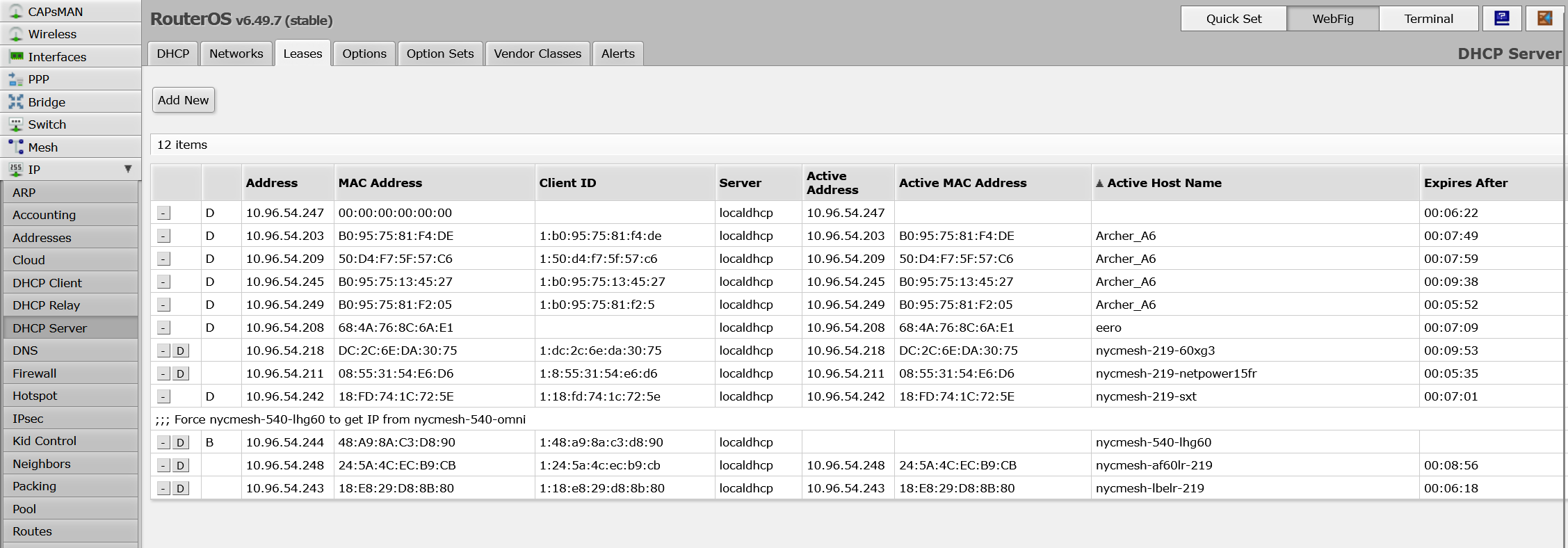
- List DHCP leases
- Show device address
- Show bridges and ports
Login and Access Terminal:
Juniper: SSH to the router's IP. Username is root. Type cli and hit enter.
ssh root@10.69.19.34
Password:
Last login: Tue Jan 16 22:17:47 2024 from 10.97.227.158
--- JUNOS 21.4R1.12 built 2021-12-17 14:37:27 UTC
root@nycmesh-1934-core:RE:0% cli
{master:0}
root@nycmesh-1934-core>List Interfaces:
MikroTik: Click Interfaces to see interface list and status.
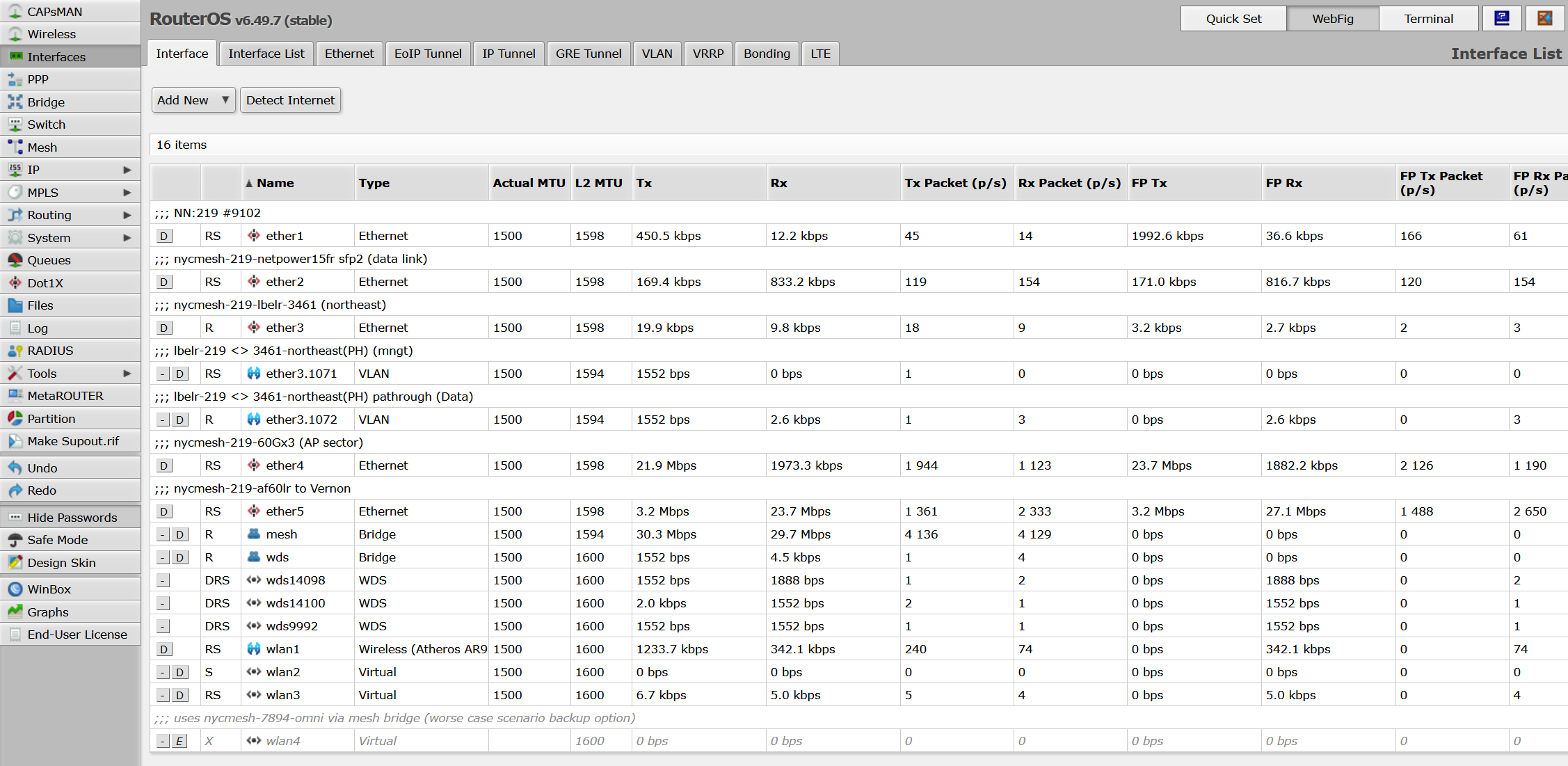
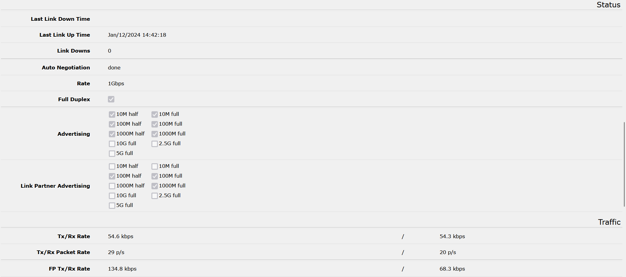
Click a specific interface to see individual status, including port status.
Juniper:
Juniper represents configuration separately from the current status. For configuration and layout of the network:
root@nycmesh-1934-core> show configuration interfaces
xe-0/0/0 {
description "Grand St OLT1 Port 1";
ether-options {
802.3ad ae0;
}
}
xe-0/0/1 {
description "Grand St OLT1 Port 2";
ether-options {
802.3ad ae0;
}
}
xe-0/0/2 {
description "Grand St OLT2 Port 1";
ether-options {
802.3ad ae1;
}
}
xe-0/0/3 {
description "Grand St OLT2 Port 2";
ether-options {
802.3ad ae1;
}
}
xe-0/0/4 {
unit 0 {
family ethernet-switching {
interface-mode access;
vlan {
members mesh;
}
}
}
}
xe-0/0/5 {
unit 0 {
family ethernet-switching {
interface-mode access;
vlan {
members mesh;
}
}
}
---(more)---For statistics and live info:
root@nycmesh-1934-core> show interfaces
Physical interface: gr-0/0/0, Enabled, Physical link is Up
Interface index: 650, SNMP ifIndex: 502
Type: GRE, Link-level type: GRE, MTU: Unlimited, Speed: 800mbps
Device flags : Present Running
Interface flags: Point-To-Point SNMP-Traps
Input rate : 0 bps (0 pps)
Output rate : 0 bps (0 pps)
Physical interface: ip-0/0/0, Enabled, Physical link is Up
Interface index: 649, SNMP ifIndex: 515
Type: IPIP, Link-level type: IP-over-IP, MTU: Unlimited,
Speed: 800mbps
Device flags : Present Running
Interface flags: SNMP-Traps
Input rate : 0 bps (0 pps)
Output rate : 0 bps (0 pps)
Physical interface: pfe-0/0/0, Enabled, Physical link is Up
Interface index: 654, SNMP ifIndex: 509
Speed: 800mbps
Device flags : Present Running
Link flags : None
Last flapped : Never
Input packets : 0
Output packets: 0
Logical interface pfe-0/0/0.16383 (Index 565) (SNMP ifIndex 510)
Flags: Up SNMP-Traps Encapsulation: ENET2
Bandwidth: 0
Input packets : 0
Output packets: 0
Protocol inet, MTU: Unlimited
Max nh cache: 0, New hold nh limit: 0, Curr nh cnt: 0,
Curr new hold cnt: 0, NH drop cnt: 0
Flags: User-MTU
Protocol inet6, MTU: Unlimited
Max nh cache: 0, New hold nh limit: 0, Curr nh cnt: 0,
Curr new hold cnt: 0, NH drop cnt: 0
Flags: Is-Primary, User-MTU
Physical interface: pfh-0/0/0, Enabled, Physical link is Up
Interface index: 653, SNMP ifIndex: 508
Speed: 800mbps
---(more)---List DHCP leases:
MikroTik: Click IP > DHCP Server, then click the Leases tab
Juniper:
root@nycmesh-1934-core> show dhcp server binding
IP address Session Id Hardware address Expires State Interface
10.70.188.20 2536927 00:18:dd:0a:19:a7 510 BOUND irb.12
10.70.188.19 3215990 00:d2:b1:58:87:46 263 BOUND irb.12
10.70.188.64 282708 02:27:22:da:a6:7c 521 BOUND irb.12
10.70.188.26 2533153 0c:62:a6:ad:ab:c5 337 BOUND irb.12
10.70.188.192 334522 18:e8:29:26:ef:25 518 BOUND irb.12
10.70.188.217 2778822 18:e8:29:59:f5:ab 586 BOUND irb.12
10.70.188.241 2536920 18:fd:74:58:20:2e 321 BOUND irb.12
10.70.188.202 2536918 18:fd:74:cb:d0:2d 311 BOUND irb.12
10.70.188.21 3207138 18:fd:74:ef:6d:8a 506 BOUND irb.12
10.70.188.132 3217186 1c:91:80:c8:51:d3 10 BOUND irb.12
10.70.188.47 50490 28:29:86:5a:f4:15 533 BOUND irb.12
10.70.188.197 2536785 28:29:86:6a:51:82 487 BOUND irb.12
10.70.188.24 2536919 28:76:10:1e:35:8e 386 BOUND irb.12
10.70.188.183 3213552 3a:e0:38:60:bb:91 198 BOUND irb.12
10.70.188.172 2416730 3c:9b:d6:75:c8:f8 571 BOUND irb.12
10.70.188.107 3216907 56:9d:3f:a6:d7:0f 57 BOUND irb.12
10.70.188.193 2604196 5c:e9:31:7c:56:ff 537 BOUND irb.12
10.70.188.130 3217152 5e:48:5d:5b:79:90 415 BOUND irb.12
10.70.188.129 3217128 5e:8f:1b:e9:16:8a 2 BOUND irb.12
10.70.188.44 1931696 60:22:32:4f:2b:fe 380 BOUND irb.12
10.70.188.136 3217238 62:45:45:e2:0a:39 500 BOUND irb.12
10.70.188.240 2857437 68:d7:9a:76:d4:f7 316 BOUND irb.12
10.70.188.203 331465 68:d7:9a:a2:07:10 453 BOUND irb.12
10.70.188.188 3213574 6a:5c:64:e1:8c:d4 439 BOUND irb.12
10.70.184.90 3026881 70:a7:41:3e:aa:91 522 BOUND irb.11
10.70.184.65 2953063 70:a7:41:3e:ab:d5 331 BOUND irb.11
10.70.187.244 2730465 70:a7:41:3e:ab:f9 336 BOUND irb.11
10.70.187.178 2476746 70:a7:41:3e:ac:51 589 BOUND irb.11
10.70.184.93 3027863 70:a7:41:3e:ac:71 318 BOUND irb.11
10.70.188.93 170763 70:a7:41:42:76:31 300 BOUND irb.12
10.70.188.45 781270 74:83:c2:9c:92:fc 394 BOUND irb.12
10.70.188.215 1945827 74:83:c2:c0:bb:90 582 BOUND irb.12
10.70.188.36 2825439 74:83:c2:c3:d1:75 354 BOUND irb.12
10.70.188.134 3147069 74:83:c2:c3:d1:83 533 BOUND irb.12
10.70.188.86 25849 74:ac:b9:0c:9a:1d 360 BOUND irb.12
10.70.188.161 71710 74:ac:b9:72:3f:33 454 BOUND irb.12
10.70.188.75 2857433 74:ac:b9:b9:92:cc 559 BOUND irb.12
10.70.188.53 2857440 74:ac:b9:bc:a7:2a 500 BOUND irb.12
10.70.188.49 2857438 74:ac:b9:bc:ab:83 346 BOUND irb.12
10.70.187.109 2182001 78:45:58:06:3c:9b 516 BOUND irb.11
10.70.187.27 573697 78:45:58:06:3c:a5 549 BOUND irb.11
10.70.187.31 573715 78:45:58:06:41:94 510 BOUND irb.11
---(more)---Show Device Address:
MikroTik: Click IP > Addresses.
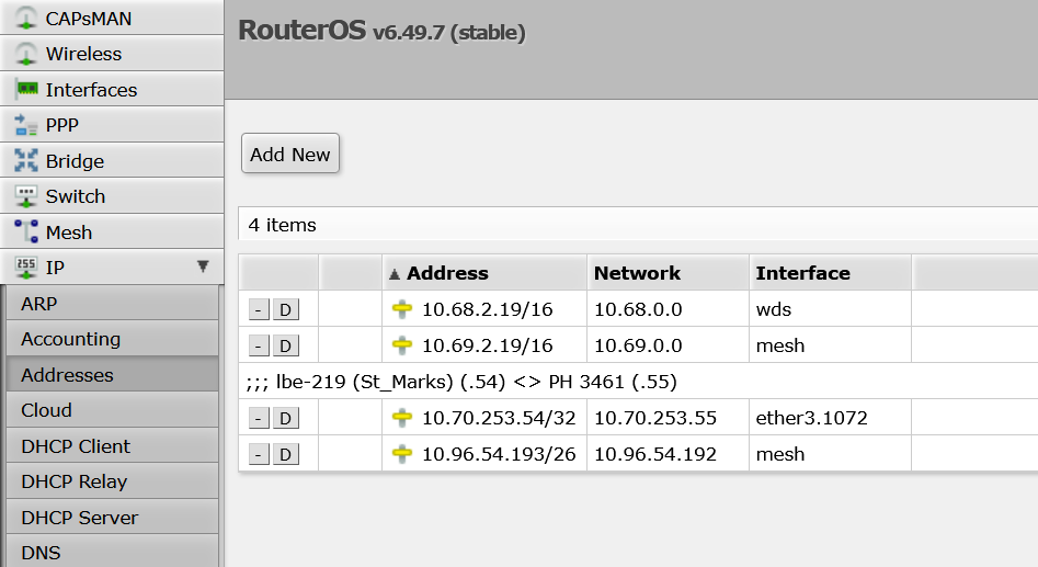
Juniper:
Every Layer 3 (IP) network is attached to an irb which in turn is attached to a VLAN, unlike RouterOS where the IPs are attached to the interfaces directly, irrespective of Layer 2 interface type.
root@nycmesh-1934-core> show configuration interfaces irb
unit 0 {
family inet {
dhcp {
vendor-id Juniper-qfx5100-48s-6q;
}
}
}
unit 10 {
description "mesh bridge";
family inet {
address 10.69.19.34/16;
address 10.70.189.1/24;
}
}
unit 11 {
description "Grand St OLTS";
family inet {
address 10.70.184.1/22;
}
}
unit 12 {
description "Grand St OOB";
family inet {
address 10.70.188.1/24;
}
}
unit 51 {
description nycmesh-1932-af24-227;
family inet {
address 10.70.251.18/30;
}
}
unit 115 {
description nycmesh-1933-mlq1-407;
family inet {
address 10.70.251.69/30;
}
}
unit 202 {
description nycmesh-1933-af60lr-7512;
family inet {
address 10.70.251.9/30;
}
---(more)---Each irb would then be attached to a VLAN, which in turn gets attached to interfaces.
root@nycmesh-1934-core> show configuration vlans
default {
vlan-id 1;
l3-interface irb.0;
}
grandstolts {
vlan-id 11;
l3-interface irb.11;
}
grandstoob {
vlan-id 12;
l3-interface irb.12;
}
mesh {
vlan-id 10;
l3-interface irb.10;
isolated-vlan sectors;
}
nycmesh-1932-af24-227 {
vlan-id 51;
l3-interface irb.51;
}
nycmesh-1932-lhg60-2463 {
vlan-id 500;
l3-interface irb.500;
}
nycmesh-1933-af60lr-7512 {
vlan-id 202;
l3-interface irb.202;
}
nycmesh-1933-eh8010-5916 {
vlan-id 302;
l3-interface irb.302;
}
nycmesh-1933-mlq1-407 {
vlan-id 115;
l3-interface irb.115;
}
sectors {
vlan-id 15;
private-vlan isolated;
}...which then get attached to interfaces (see above).
Post Install (New Member Form)
This is a template form to print and leave with members with their WiFi information, install/node number and other details. It also provides links to our support channels if they have any issues.
Our Mesh Guide also includes a page to write down this information. Otherwise writing the WiFi information on a piece of paper is also acceptable.
Remember to write down the administrator (management) password for WiFi router. This is important if the member needs to change their WiFi password later. (Most installers have a standard password that they use, but it's helpful to have a record so we don't need to reset the router if we don't know it)
Common Issues and How to Avoid Them
Alignment and wind
We've had many antennas lose alignment in the wind. There's a few simple things you can do to prevent this-
-
Use a socket and drill to tighten hose clamps fast. It's hard to get the hose clamp tight with a screw driver. A socket and drill will get it really tight. You'll need a socket set that has both american and metric sockets.
-
Put one layer of electrical tape under the hose clamp. This can help stop slipping, especially on smooth j-pipes like the Ubiquiti ones.
-
Make sure pipe mounts can't twist by putting a bolt through them. You'll need a set of metal drill bits (such as titanium) and some 2 1/2" long 1/4" bolts.
If you can move the LiteBeam with your hands, it will also move in the wind. Larger antennas, like the LiteBeam LR need even more care to stop them from moving in the wind.
Bad crimps
Ethernet testers aren't perfect so you need to check your crimps visually-
- Wires are in correct order!
- All wires are pushed all the way to the end
- All pins are pushed down after crimping (important!)
- The cable jacket is just inside the RJ-45
If the first three things are correct the cable will work! The jacket being inside the rj-45 gives it a bit more strength.
It is possible that the cable tester will wrongly say it is fine even if the wires aren't at the end and the pins aren't all down.
The crimping tool's job is to push the pins into the wires. Look at the pins before and after crimping and you should see that they are all pushed down by the same amount. Some crimping tools are incompatible with the toughcable jacket and are unable to push the pins down evenly. We recommend this crimper
Not enough cable
To save carrying a full box of cable many installers take a roll of cable (and occasionally not enough)
Here’s a short guide to help:
- Tough cable is marked every meter. Each box is 305m so if the end says 255m you have 50m left
- 50 meters of cable is enough to do an average install
- Each floor adds about 3 meters to the length
- Member’s floor info is now on the schedule to help with calculation
- Each extra apartment adds about 20m + floor calculation
- 100m is the max length for Cat5 cable. (data loss and voltage loss is too much)
- If you have a roll, you can measure one loop and multiply by the number of loops
1 meter = 3 feet
OmniTik power problems
The biggest confusion with OmniTiks is that one model has POE out (OmniTik POE) and one doesn't. They both look the same. There is obscure print near the ethernet ports that will tell you if it is ethernet out. OmniTik POE has a much larger power injector and this must be used to power it. If you accidentally power it with a smaller adapter it will work but the LiteBeam will occasionally reboot.
Sometimes the OmniTik won't automatically power the LiteBeam. You can force on the power by going to Webfig>Interfaces>ether5 and select "PoE Out: forced on". Also check that you are using the correct power injector for the Omni as this can also cause this problem. If the "PoE Out" option is missing you have the wrong kind of OmniTik!
Use electrical tape to tape the small DC power cable to the white injector after plugging it in. This often comes undone causing all sorts of problems. The DC power cable is the same as the tp-link DC cable, and will break the tp-link if you plug it into that instead.
The OmniTik should plug directly into a wall, not a power strip to avoid accidental power loss.
Query
This page works best in incognito/private window mode!
This is for installers to query our install spreadsheet. This is password protected.
If you have trouble running this script, try using an incognito (private) window in your browser
This uses simple matching for addresses. Type the number and street name, e.g. "123 Smith St". Don't enter a complete address! For NN, install number and email it uses exact matches.
Safety
Growing the mesh is important, but so is staying safe to install more nodes. These are general safety guidelines intended to address more common hazards on an install, but keep an eye out for risks even if they are not covered here.
What to Bring to Site
In addition to standard installation equipment, bring the following gear to ensure safety on site:
- Fully-charged cell phone
- First-aid kit
- Eye protection
- Gloves (optional, but may come in handy if moving anything dirty)
- Boots or sturdy closed-toed shoes (nothing fancy; they will get dirty)
- Sunblock and hat (in summer)
- Water
- Cold-weather apparel (in winter - rooftops tend to be windy)
- Allergy medication (consider indoor as well as outdoor allergens)
Traveling to and from Site
Be aware of your surroundings at all times. If you feel unsafe traveling to a particular location, consider meeting up with co-installers beforehand and traveling together.
Site Survey

Ask your member to tell you about any hazards on site.
During your site survey, note potential hazards and tell your fellow installers. These may include:
- Loose cables
- Overhead power lines
- Locking doors
- Ladder defects
- Glass, needles, nails and other sharp objects
- Biohazards, such as insects or animal waste
- Puddles and ice patches
- Skylights
- Unsecured, damaged or absent parapet walls and fences
Working with Others
Take responsibility for your own safety first but make sure to watch out for your co-installers.
If you are an install team leader, understand the capabilities of your fellow installers and assign tasks they are comfortable doing.
Inform your fellow installers of any medical conditions that could impact the install.
If you are asked to do something you find unsafe, respectfully decline the task and propose an alternate method.
Weather
Read the weather forecast the day of the survey. If there is a high likelihood of poor conditions, cancel the install.
In case of heavy rain, thunder or lightning, leave the roof immediately and cancel the install.
During hot weather, stay hydrated and protect your skin with sunblock. Take breaks indoors or in the shade. Recognize the signs of heat exposure, such as dizziness, nausea, headache, confusion, and rapid, shallow breathing.
During winter, tread carefully to avoid slips and falls on ice. Stay away from icy patches when possible.
During cold conditions, protect your skin with appropriate outerwear and take breaks indoors to warm up. Recognize the signs of cold stress, such as uncontrolled shivering, slurred speech, clumsy movements, fatigue and confused behavior.
During windy conditions, keep lightweight equipment inside a bag so that it does not blow off the roof.
References and further reading:
- https://www.ccohs.ca/products/posters/pdfs/keepyourcool.pdf
- https://www.ccohs.ca/oshanswers/phys_agents/cold_working.html
Avoiding Falls

Rooftops present various falling hazards. Exercise caution while working on rooftops at all times.
Ask your member about any hazards in advance of entering the rooftop.
Move carefully and watch where you are walking at all times. Try to avoid stepping backwards.
Keep yourself and your equipment away from the edge of the roof whenever possible.
Step carefully over or around loose cables, debris and other tripping hazards.
Don’t grasp or put any weight onto unstable parapet walls or fences.
Do not step on, lean against or put any weight on skylights. Do not place any equipment on skylights.
When working near the edge of the roof, maintain visual awareness of the edge at all times. Do not work facing away from the edge.
Keep off steeply pitched surfaces.
References and further reading:
- https://simplifiedsafety.com/blog/top-10-rooftop-safety-hazards/
- https://www.osha.gov/Publications/OSHA3755.pdf
- https://www.buildings.com/article-details/articleid/18484/title/best-practices-for-roof-safety/viewall/true
- https://www.cdc.gov/niosh/docs/2004-156/pdfs/2004-156.pdf
Access Hazards and Confined Spaces

Understand egress (exit) routes from the rooftop space. If there is a door or a hatch, make sure that it does not lock behind you. Prop open if necessary.
Avoid entering confined or narrow spaces.
References and further reading:
Fixed Ladders to the Rooftop
Inspect the ladder prior to using it. Make sure it is secured to the wall and that rungs are stable and not slippery.
Only one person on the ladder at a time.
When climbing through a narrow passage, make sure to take off any loose-fitting clothing. If carrying a backpack, ensure you have enough clearance behind you.
Always maintain 3-point contact (i.e. only let go and move one hand or one foot at a time). Do not carry anything that compromises your ability to grip the ladder or could cause you to become imbalanced.
Work together with your co-installer to pass equipment up to the top or bottom of the ladder. Inform your co-installer of the weight of anything you are passing to them. Make sure they securely grip the equipment before letting go.
Face the ladder when climbing.
References and further reading:
Temporary Ladders
Inspect the ladder prior to using it. Use the ladder only on a stable and level surface..
Always maintain 3-point contact. Do not carry anything that compromises your ability to grip the ladder or could cause you to become imbalanced.
Never stand on the top step, the paint tray, or thin support struts on the back which are not meant to be stepped on.
The proper angle for setting up a straight ladder (not the self-supporting A-frame type) is to place its base a quarter of the working length of the ladder from the wall.
Do not place a ladder on boxes, barrels or other unstable bases.
If using an extension ladder, make sure the locks are engaged on both sides.
References and further reading:
- https://www.osha.gov/OshDoc/data_Hurricane_Facts/portable_ladder_qc.pdf
- https://www.creighton.edu/fileadmin/user/AdminFinance/Facilities/EHS/docs/Training/Ladder_Safety.pdf
Electrical and Cable Safety**

The equipment used in a typical install is classified as low-voltage beyond the electrical outlet adapter. Low-voltage electrical circuits still present a shock hazard.
While the shock from a low-voltage cable may not cause serious injury by itself, it could cause you to jump or lose balance, which could result in a fall.
Learn to identify high-voltage electrical equipment and stay away from it.
Be careful to not cut or drill through concealed piping or wires. Make a small inspection before starting to cut or drill.
Keep cables away from power wires, lightning rods, transformers, hot pipes and mechanical rooftop equipment such as air conditioning units. These things can get hot and melt the coating off our cables.
Never install wiring during electrical storms.
Use tools with non-conducting handles.
Make sure to secure cable to rooftop and wall surfaces, and keep it out of the way as much as possible. Do not create a tripping hazard for your member or other building users.
Make sure to clean up cable sheathing after stripping. A pet or child might eat them if left on the floor.
References and further reading:
- https://www.ecmag.com/section/miscellaneous/low-voltage-not-low-risk
- Avoid electric shock by carefully handling low-voltage wiring
- https://electrical-engineering-portal.com/21-safety-rules-for-working-with-electrical-equipment
Drill Usage
Inspect the drilling area before starting to identify any objects that might get in the way, such as electrical cables, nails or staples.
Get a secure footing when operating the drill. Do not overreach.
Select the correct bit. (See installation slide deck)
Make sure you are using the right bit for the material you are drilling into and ensure the drill bit is in good condition.
Tighten the chuck securely.
Use eye protection, especially when drilling through metal. Metal will shred, and shards could fly into your eye.
Keep the drill away from water. Move the drill to a dry location if it starts to rain.
Clean the drill bit after operation.
Report any damage or defects to the tool owner if you are borrowing it.
References and further reading:
- https://ehs.yale.edu/sites/default/files/files/powered-hand-drill.pdf
- https://www.ccohs.ca/oshanswers/safety_haz/power_tools/drills.html
Moving furniture
Coordinate the moving of any heavy furniture with the member.
Before moving anything, plan the move and communicate the plan it to your member or fellow installer. Consider where you will pick it up, where you will move it and identify any tripping hazards.
Make sure nothing will fall off the furniture you are moving or that moving the furniture will not cause something else to fall.
Get as close to the load as possible. While lifting upwards, keep your back straight and your knees bent, and do not twist your body.
Do not lift anything that is too heavy for you to pick up in a smooth motion.
If moving any outdoor items (for example air conditioner supports), pick up cautiously as there may be insects underneath.
References and further reading:
Asbestos
Buildings in New York City may contain asbestos. Learn how to identify materials that may contain friable asbestos and avoid exposure (see link below).
Asbestos is considered to be not dangerous unless damaged or disturbed, which can release fibers into the air.
A general rule of thumb is to assume asbestos may be present in homes built before 1980.
Materials that commonly contain asbestos include:
- Ceiling tiles
- Vinyl floor tiles and carpet underlay
- Siding shingles, stucco and transite
- Insulation
- Adhesives
- Old switchboards
Learn how to visually identify asbestos. Here is one resource: https://web.archive.org/web/20220821044546/https://merryhill.co.uk/what-does-asbestos-look-like/
References and further reading:
- https://www.maacenter.org/blog/how-to-identify-asbestos-a-brief-guide/
- https://web.archive.org/web/20220821044546/https://merryhill.co.uk/what-does-asbestos-look-like/
- https://inspectapedia.com/hazmat/Asbestos_Identification.php
Liability
The property owner may face liability for any injury. Maintaining safe work practices helps protect your member as well as yourself and your fellow installers!
Read more about homeowner liability here: https://realestate.findlaw.com/owning-a-home/homeowner-liability-safety.html
Further Reading
- OSHA Publications
- Canadian Center for Occupational Health and Safety
- Health and Safety in Rooftop Work
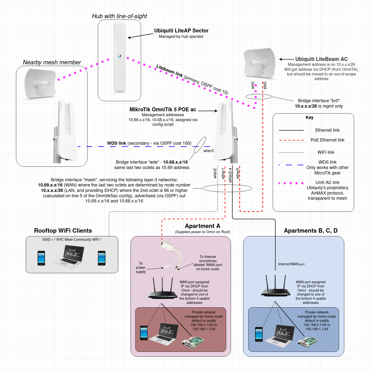
Typical Install Diagram (Omni & Litebeam)
The purpose of this diagram is to give a technical overview of the typical LiteBeam + Omnitik5ac install described in the Typical Installations page - scenario 2
NOTES
-
The last two octets of the 10.68.x.x/16 and 10.69.x.x/16 (mesh backbone) addresses are determined by node number
-
The last three octets of the 10.x.x.x/26 (member side of the OmniTik) network are also determined by node number and are calculated by the OmniTik5ac config on line 5. Each NYC Mesh LiteBeam/OmniTik installation has one of these unique /26 networks on the member side of its OmniTik. The OmniTik provides DHCP to this network, with the bottom and top 5 usable addresses being left out of the scope (for static assignment to home-routers, LiteBeam management etc). DNS is provided by 10.10.10.10. This 10.x.x.x/26 network is redistributed to the mesh backbone via OSPF.
-
This diagram was created on app.diagrams.net (formerly draw.io). The diagram source is attached to this page.
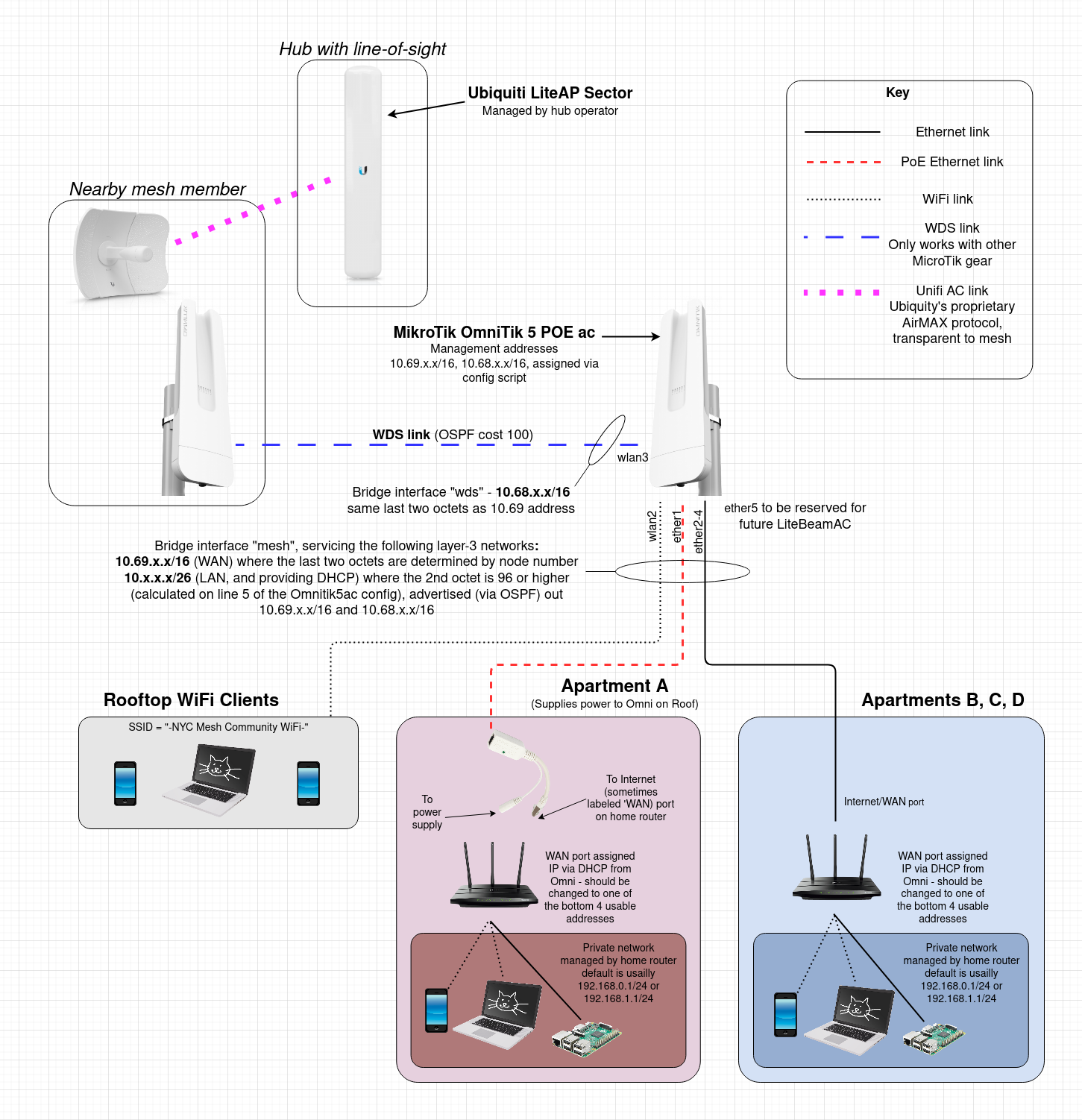
Typical Install Diagram (Omni-only)
The purpose of this diagram is to give a technical overview of an Omnitik5ac-only install. This type of install should only be done if it is impractical to also install a LightBeamAC (e.g. no line-of-sight to a hub). Both types of installations (with and without LiteBeamAC) are depicted in the Typical Installations page - scenario 2
NOTES
-
The last two octets of the 10.68.x.x/16 and 10.69.x.x/16 (mesh backbone) addresses are determined by node number
-
The last three octets of the 10.x.x.x/26 (member side of the OmniTik) network are also determined by node number and are calculated by the OmniTik5ac config on line 5. Each NYC Mesh LiteBeam/OmniTik installation has one of these unique /26 networks on the member side of its OmniTik. The OmniTik provides DHCP to this network, with the bottom and top 5 usable addresses being left out of the scope (for static assignment to home-routers etc). DNS is provided by 10.10.10.10. This 10.x.x.x/26 network is redistributed to the mesh backbone via OSPF.
-
This diagram was created on app.diagrams.net (formerly draw.io). The diagram source is attached to this page.
Typical Installs
Please read our FAQ if you haven't already.
The intention of this page is not to be technical but rather give to the non-technical person an understanding of a typical installation.
NYC Mesh is an "over the air" network. The aim is to connect rooftop to rooftop using different types of equipment based on geography and topology. And in doing so, to expand NYC Mesh network coverage to the next block and so on*. The idea of NYC Mesh is to share the connectivity with neighbors, share resources, share equipment, share the network. Create a community of communities connecting to each other.
NYC Mesh typically uses two categories of equipment.
-
In the first category is equipment that "speaks" AirMAX (AirMax protocol).
Some hubs and supernodes have antennas covering a sector, or 360°, that "speak" AirMax. To connect to those, you need to install on your roof an antenna that understands that same AirMax protocol (see Ubiquiti equipment).
In addition, some hubs may as well have antennas of the second category. -
The second category of equipment uses the same wifi as your home router, 802.11 (there are different versions of wifi- 802.11a/b/g/n/ac) (see Mikrotik equipment).
*Note: In some cases, such as large buildings we may use fiber to connect but would setup a rooftop "hub" to expand the network to surrounding neighbors.
1.- Connect to a hub or supernode (one apartment - no roof-to-roof expansion). Such installation does not allow expansion of the Mesh network, nor allow sharing with neighbor community
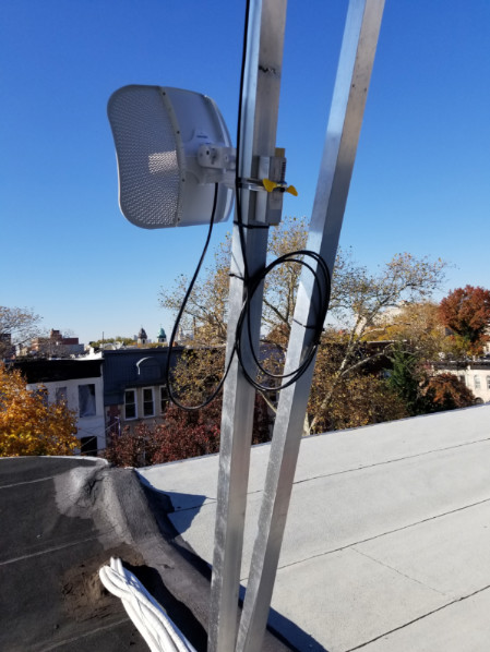
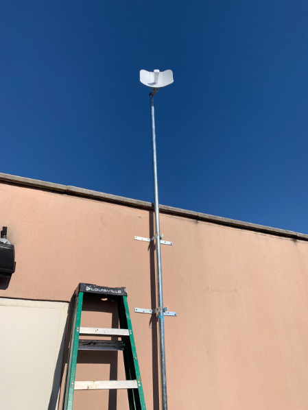
A typical installation has a LiteBeam antenna on the roof. From that antenna an ethernet cable is run to the apartment. (note: the antenna is sometimes referred to as the outdoor router).
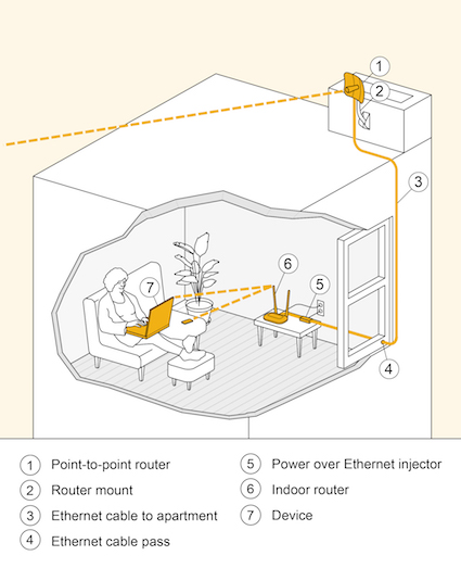
Depending on the roof it can be mounted on an old TV antenna pole, on an added pole, a wall, a chimney, or any existing infrastructure.
In the apartment any type of WiFi router can be installed. We install a TP-Link router.
2.- Connect to a hub or supernode (one or several apartments - with roof-to-roof expansion). Allow Mesh network expansion and sharing with the neighbor community
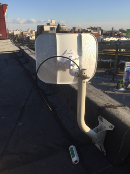
To allow others to connect to your rooftop LiteBeam router we need to add an ethernet router and an access point. For this we usually use an OmniTik mounted on the same pole or it can be mounted somewhere else on the roof. The OmniTik will give you wifi on your roof and also allow 4 other apartments to connect with ethernet.
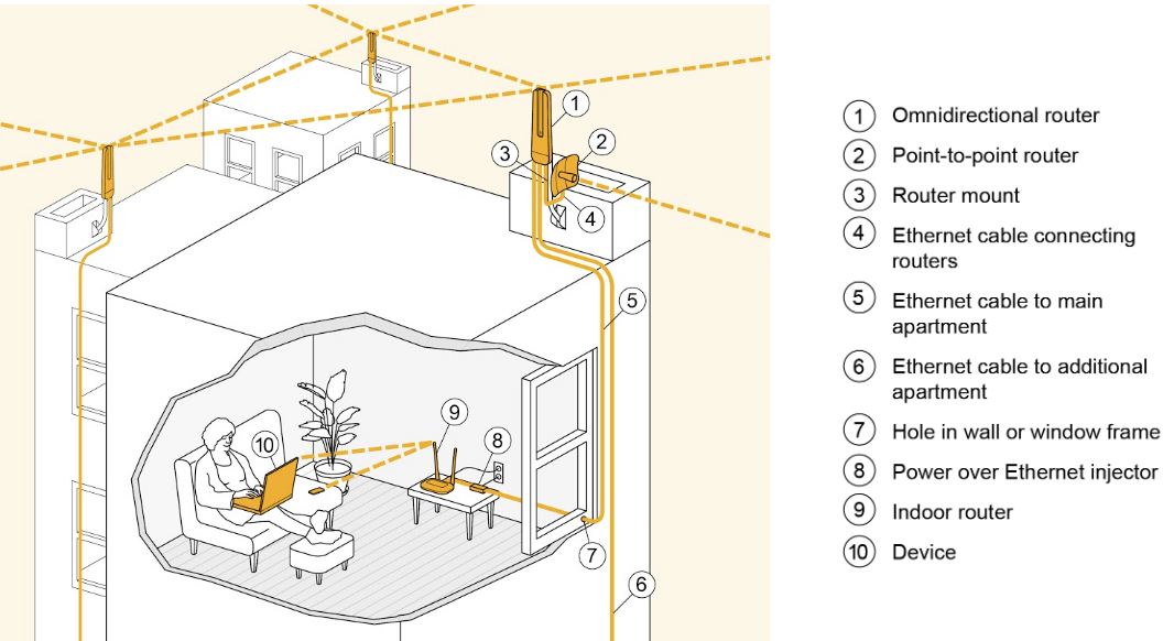
The OmniTik is an Omnidirectional (360°) antenna. It has about 2-3 block radius. We connect the Litebeam to the OmniTik and apartments to the OmniTik via ethernet.
OmniTik not located next to the Litebeam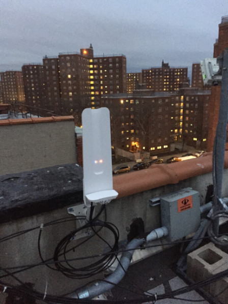
Other rooftops can connect to the OmniTik by using another Omnitik if they are close enough or we use, in some cases, an SXT.
This setup as a major benefit. It allows the devices to mesh with each other. If an other Omnitik is installed in a 2-3 blocks radius they will connect to each other and create a mesh, thus improving reliability and allowing a) the Mesh network to expand, and b) the neighbor community to use it to access internet.
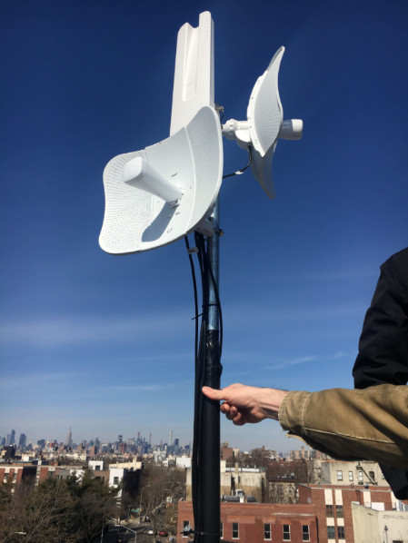
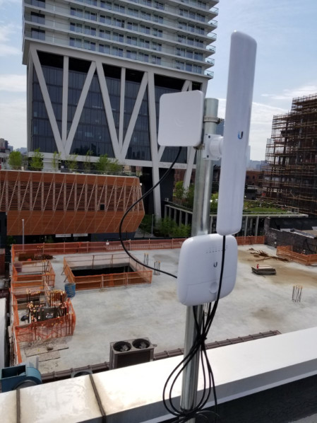
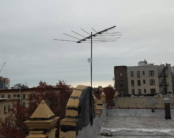
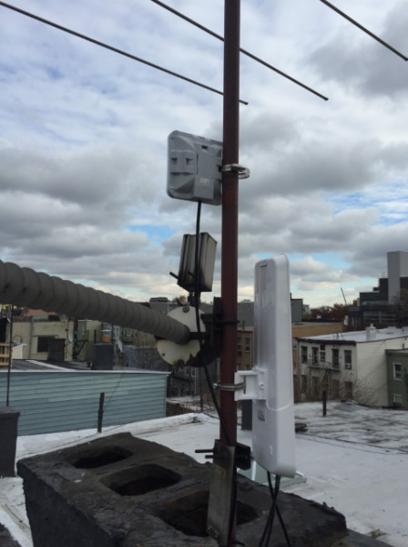
3.- A good rooftop can be "beefed up" to allow for more connectivity.
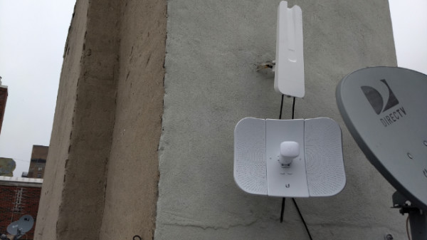
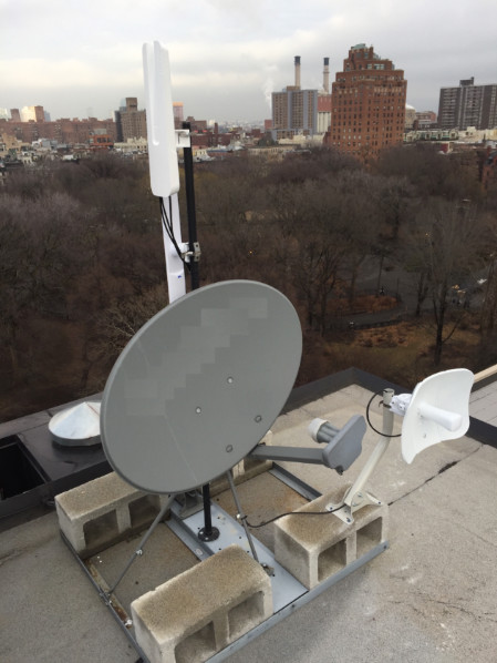
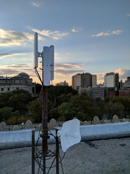
If the rooftop is interesting (at a good location, it's high enough, etc) we may install "sectors" or other type of equipement. Sectors are antennas that communicate via Ubiquiti's AirMax protocol and have a longer range than an OmniTik. Additionally, we may connect to two hubs, etc....
Here are four examples.
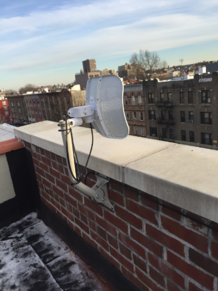
4.- A building can connect to another building with an OmniTik using a different antenna
A building can connect to another building with an OmniTik using a SXT antenna. It can then serve one or several apartments.
Those are typical installations. Other setups are possible and in use throughout NYC Mesh.
For the most up-to-date overview of the entire install process, check out the Install Training Presentation.
Siklu Alignment
Alignment Process
Under Construction
Link Budget Calculator
The Siklu Link Budget Calculator predicts link availability in a given location. This should be done first, to calculate optimal signal levels. We can use this information when when performing fine alignment with a digital multi-meter.
Video: How to use Link Budget Calculator
Video: Siklu Etherhaul Antenna Alignment
Coarse Alignment
Coarse alignment should be done after mounting the antenna.
Video: Coarse Alignment
Fine Alignment
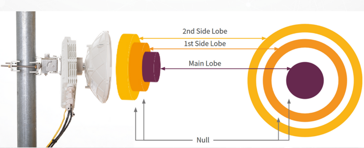
The Siklu radiation pattern has multiple "lobes," a bit like two concentric donuts (side lobes) around the center target (main lobe). These are effectively "lumps" in signal strength emitted by the antenna. Like a mountain top there are many local peaks, but only one true highest point.
Video: Aligning Large Form-Factor Radios
To align the Siklu:
- sweep through all these lobes in pitch and yaw
- record the signal strength values
- determine the maximum signal strength nearest the expected RSSI according to link budget calculator
- finally align the antenna at this maximum position and bolt it permanently in place
Alignment Tool
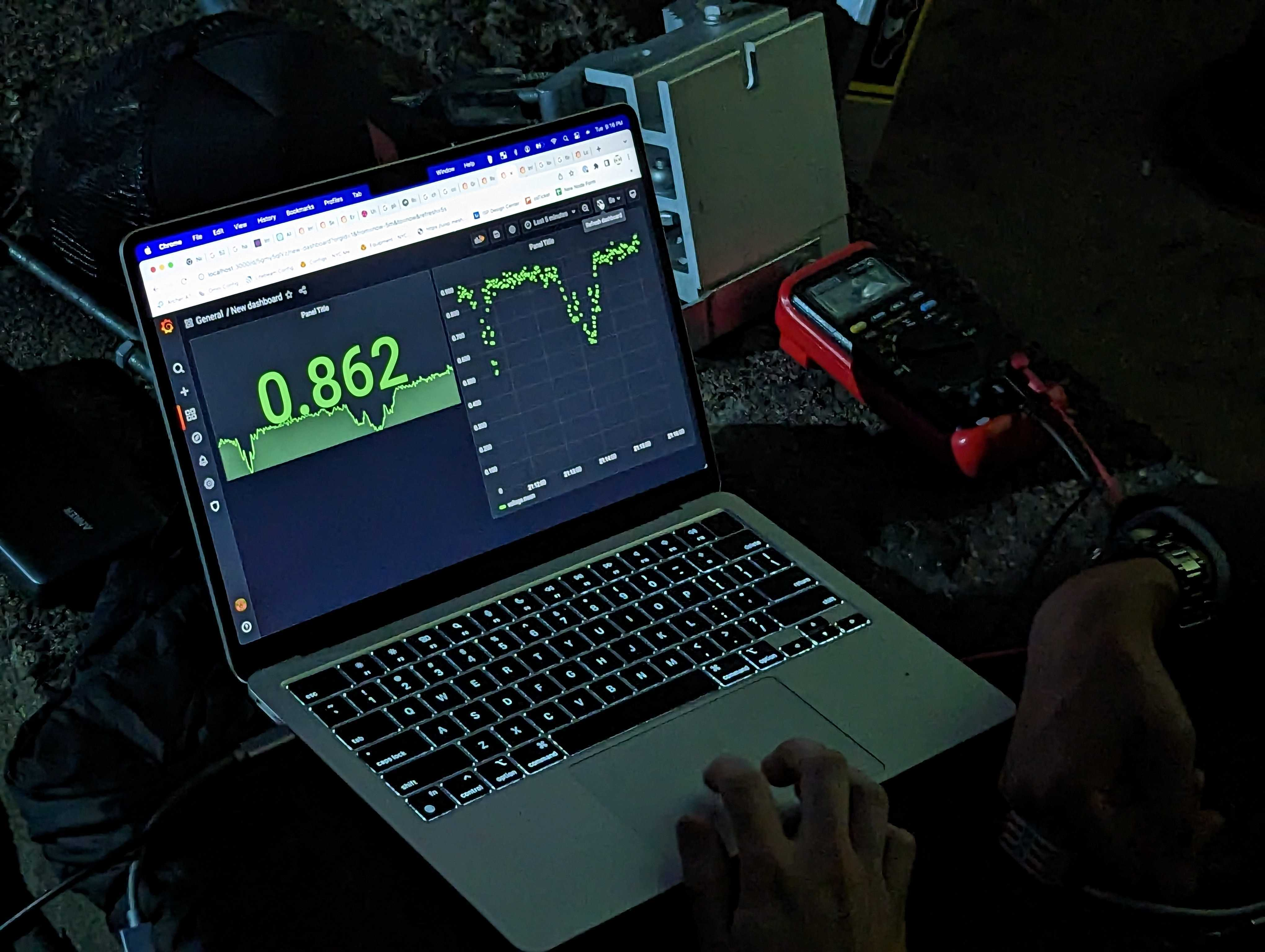
A system of digital output multimeter and logging software can aid in the alignment process. This software creates a Grafana graph of the signal strength / lobes, removing the need to manually record with pen and paper.
Video: Using a Digital Multi-Meter to Perform Fine Alignment
Software:
Hardware
TP4000zc multimeter (Ask Andy to borrow the meter + cables)
See Also:
Siklu, before its aquisition by Ceragon in December 2023, had a very helpful technical support staff. Since then, a lot of the Siklu documentation has disappeared from the website, only a support email is provided. Luckily the Siklu YouTube channel still exists, we still have some guides squirreled away in this Master Drive Folder. Notably:
- EtherHaul 8010 Series Installation and Operations Manual
- Siklu Antenna Alignment Technical Training Slideshow
- Do's and Don'ts on the Alignment of Siklu's 2ft Antenna
Ubiquiti Unifi AP Adoption Guide (WORK IN PROGRESS)
Introduction (Why we need to do this):
Ubiquiti WiFi access points need a controller (Unifi) to be configured, as they can't operate as standalone devices.
For the mesh, this controller resides on a virtual machine in the SN3 data center.
In a "normal setup" in an office building or somewhere, the AP devices are all on the same LAN and are plugged into a Unifi switch, so they will be auto-detected by the controller and can easily be adopted.
This intended setup rarely happens on the mesh, as the AP may be on the other side of the city from the controller, with various firewalls and filters in between. This means the device won't automatically find the controller and the controller won't be able to adopt the device, so your fancy new WiFi access point remains a paperweight.
However there is a way to help the process along...
We do this by logging into the device (SSH) and telling it where the controller is located (it's IP address). Once this is done the device will announce itself to the controller and can usually be adopted without issue.
Note: You can't adopt WiFi Mesh AP devices via a wireless only connection. You need to connect them with a wired interface first to adopt them, then you can unplug them and move them to their final location. They will then be able to operate in a WiFi mesh setup using another AP as their uplink.
Prerequisites:
You will first need to know the IP address of the Access Point. If you're plugged into an Omni, this can usually be found by looking in IP > DHCP Server > Leases Tab. Look for a device called "Unifi" or "UAP-Pro" or something like that. Write down what IP it has and set it to a static IP while you're at it.
If you can't find the device in the leases tab, you may need to Torch the port to find the IP.
Go to Interfaces > Interface List and click the interface to which the AP is connected. (ether3 on the Omni or whatever)
Click "Torch" in the top menu bar, then click "Start".
At the bottom of the screen you will see a list of connections on that port. Usually the IP of the access point should show up in the "src" column, though there may be a couple others, so wait a second and choose the most prominent IP.
Next you will need a computer from which you can SSH
Pretty much any windows/mac/linux computer will work:
- For Windows: Windows Key then type "cmd" and hit enter to open a terminal window.
- For Mac: Command Key + Space, then type "Terminal" and hit enter.
- For Linux: If you're already running Linux, you should know this...
Instructions:
1. Once you you have the terminal open, type ssh ubnt@<device IP address> and hit enter.
You may need to type "yes" to accept the unknown SSH certificate.
When prompted for a password the default is "ubnt"
2. You should reach the landing screen of
Omni PoE Diagram
Fiber Optics
Fiber Safety
1. Intro
1.1 Description
Although fiber is a relatively safe material to work with, there are some hazards to be aware of. These hazards can be particularly troublesome since bare fiber is microscopic and transparent; it is nearly impossible to detect if you lose track of your scraps.
They come in two forms:
- fiber scrap
- fiber shard
1.2 Details
There are some details to keep in mind while reading this page:
- The fiber cable refers to the glass fiber, cladded and wrapped by both inner and outer jackets.
- Bare fiber refers to the glass core that is left after stipping the outer and inner jackets as well as the cladding.
- The cable is spooled in the package; the curvature is a hazard as the cable will bend back quickly when straightened out.
- Bare fiber is extremely fragile.
- Positioning the fiber on the cleaver or splicer is a delicate operation. The fiber is likely to poke a hard surface and bend, leading to breakage. If not careful when unclamping the cable, it will jump out of the tool and back into shape as mentioned in (3).
- Once fiber gets in your body, it may never leave as it neither decays or get broken down by the immune system.
- Using a microscope to locate fiber is only possible on skin and is extremely challenging due to the scale, the elasticity of skin, and uneven surface of the skin.
- The hazards can also affect others who are currently in the space or will be in the future.
2. Fiber Scrap
2.1 Description:
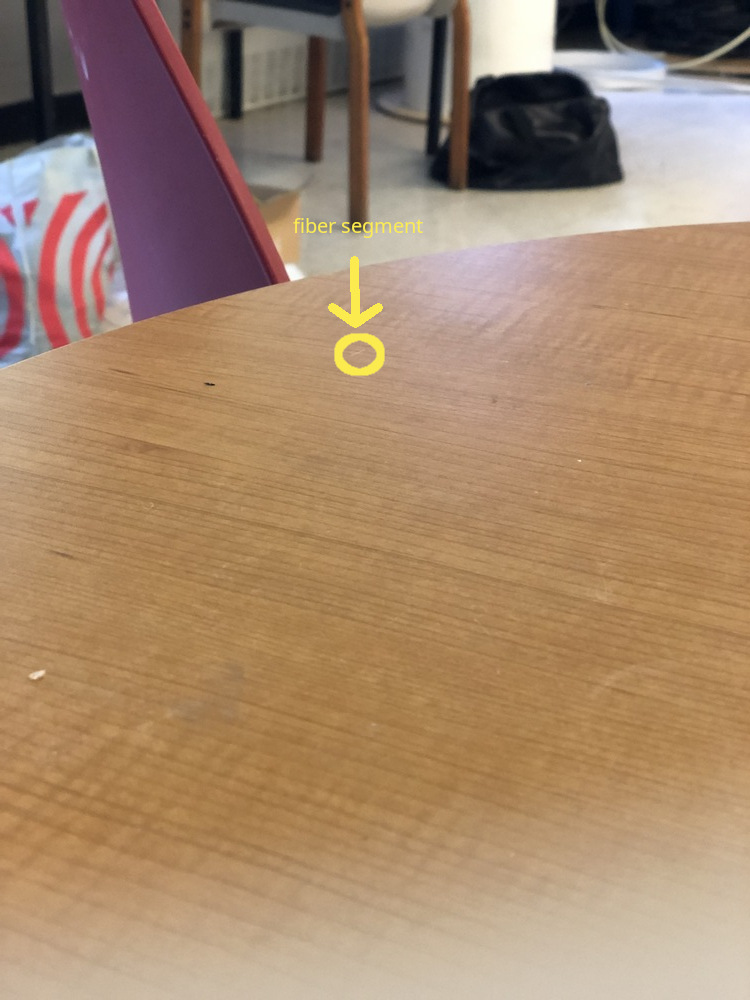
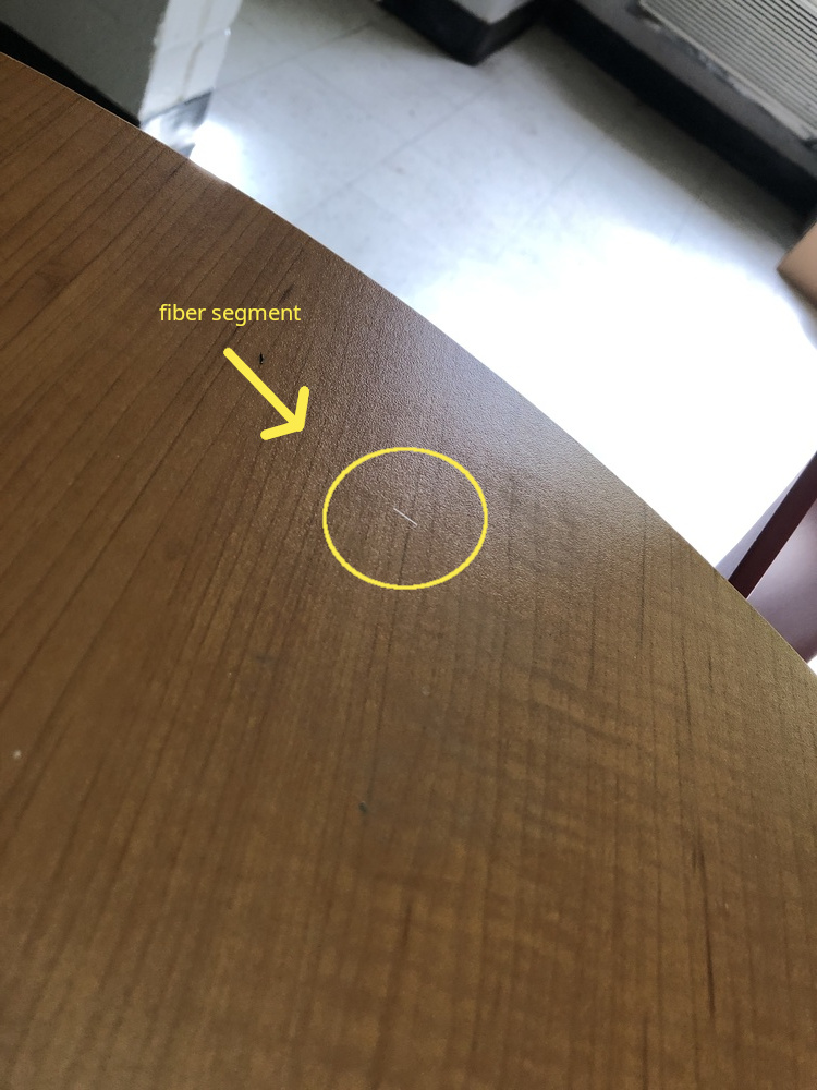
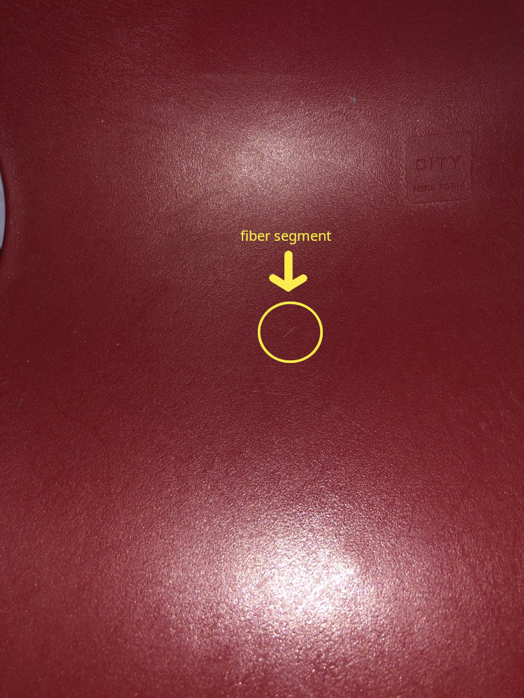
A piece of fiber scrap is a segment of bare fiber which gets created while cleaving or accidentally breaking bare fiber. Scraps can break down into smaller segments or into shards. They are the easier pieces to keep track of due to their length. If a scrap disapears, shining a flash light at different angles on a surface will produce a segment shaped glimmer if it hits a scrap.
As shown in the pictures bellow, the amount of light and angle at which it hits the scrap affects the visibility. Note that these are two different pieces of scrap, which were found by closely inspecting the surfaces using a flashlight.
2.2 Hazards:
There are two ways in which scraps are hazardous; pricking and snapping.
-
pricking
How:
Pricking can occur when the cable flicks back into shape and hits exposed skin, when attempting to grab scraps with bare hands, or when touching/sitting on a surface which happens to have unseen scrap(s) on it.
Consequence:
Pricking can lodge splinter or shards bellow the surface of the skin.
Mitigation:
PPE (rubber gloves, eye protection with side shields, coveralls, dark mat work area). -
snapping
How:
Snapping can either occur when the cable flicks back into shape or when bending the fiber too far when positioning the fiber on the cleaver or splicer.
Consequence:
Snapping can send both a scrap and shards flying; These can land on food, in the eyes, on the surface of the skin, and shards can be inhaled.
Mitigation:
No food or beavarages around, PPE (rubber gloves, eye protection with side shields, coveralls, dark mat work area, plexiglass sheet).
2.3 Potential consequences
-
Ingesting scraps can cause internal hemoraging.
-
Lodging scrap or shards bellow the skin will cause discomfort, and potentially cause infection.
-
Shards' potential consequences are addressed bellow.
3. Fiber Shards
3.1 Description:
Fiber shards are microscopic glass shrads; similar to fiberglass dust. They are nearly impossible to track due to their size; the smallest shards can be measured in micrometers (1 micrometer is 1/1000th of a millimeter).
3.2 Hazards:
- dispersion
How:
Due to their size, the smallest shards can be carried by air currents.
Consequence:
Shards can be inhaled, land on skin, eyes, clothes, food/beverage or nearby surface to be picked up later.
Mitigation:
The space needs to be well ventilated, no food or beavarages around, PPE (rubber gloves, eye protection (side shields), coveralls, dark mat work area, respirator designed for the hazard).
2.3 Potential consequences
-
Ingestion can cause inflamation and potentially internal hemoraging.
-
Shards in the eyes or on the surface of the skin can cause inflamation.
-
The Washington Department of Health claims that 1) Depending on the shards' size and shape, they may be biopersistant, 2) on the short term, inhaled shards will cause inflamation in the airways and exacerbate existing issues, and 3) on the long term, unlike for asbestos, lung disease rates of workers chronically exposed to fiberglass dust are "not consistently different from what is found in the United States general population". This source claims that this is due to the different structures of asbestos and fiberglass; that they break differently.
4. DOS AND DON'TS
DO:
- Clean up any cluter before handling fiber.
- Use PPE (e.g. eye protection or face visor, disposable coveralls, black rubber gloves ...).
- Wear dark clothes to spot scraps/shards more easily.
- Handle fiber over black, non-reflective surface.
- Handle fiber in a well lit and ventilated area.
- Pick up fiber fragments/scraps with tweezers (preferably rubber coated for better grip and lower risk of breakage).
- Frequently clean surfaces with adhesive tape (NOT a brush) to catch stray pieces. FOLD THE TAPE ONTO ITSELF BEFORE DISPOSING IT.
- Use tape to remove fiber coating from 3rd hole of stripping tool (since it may contain shards).
- Wash your hands after handling fiber.
- Dispose of fiber fragments and scraps in a suitable container; tape used to catch scapes should also go in that container.
- Follow systematic cleaning routine for your work area and all the equipment to avoid leaving scraps or shards behind.
DON'T:
- Touch fiber with bare hands.
- Touch your face after handling fiber.
- Blow dust or scaps off of a cleaver or fusion splicer, or any surface that looks dusty.
- Throw stripped material on the ground (stripping the coating can create shards).
- Look directly into plugged fiber to try to see lazer or infrared light ( infrared is invisible anyways).
- Eat or drink around fiber.
- If the segment is not visible, move your head around the cleaver or use a flashlight to make the glass shine; it may be on the top pad of the cleaver. DO NOT PICK UP THE CLEAVER AND FLIP IT UPSIDE DOWN; ESPECIALLY NOT ERRATICALLY. THERE IS NO REASON TO DO SO AND ONLY MAKES IT HARDER TO FIND THE SCRAP AS IT MAY FALL OFF.
5. RECAP
Hazard origins
Cleaving
-> scrap
-> shards
Cutting cable
-> shards
Snapping scrap
-> scrap
-> shards
Stripping jacket/cladding
-> shards
Hazards
Scrap
-> pricking
-> ingestion
Shards
-> inhalation
-> ingestion
-> skin, eye contact
Potential Health Consequences
Ingestion -> inflamation, internal hemorage
Inhalation -> airway inflamation
Pricking -> infection
Skin, eye contact -> inflamation
Bonus
Although risks are low for a few installs, over the long run, some installers may want to take more precautions. An extremely safe setup for the most risk averse of installers would be a DIY fume extractor. This setup is compact and mitigates all of the hazards mentioned in the previous sections.
The plexiglass walls contain any dust in a small area, the gloves protect the installer's skin and clothes, and the negative presure fan ensures proper ventilation. In addition, hooks and magnets can be used to keep some tools organized and permanently inside the container (e.g. stripping tool, tzeezers, alcohol pads...). In order to perform a splice near the ceiling, some mechanism needs to be used to strap the container atop a ladder (unless the installer considers a baker scaffolding affordable and convenient)
Equipment list:
- fume extractor ( < $200)
- 6 18*24 acrylic sheets + acrylic cement + small hinges OR large, clear plastic box (plastic box may not be as practical as custom acrylic box)
- 4 inch hole saw
- 4 inch pvc pipe
- plastic epoxy
- 2 worm clamps (for the gloves on the extractor)
- gooseneck arms with aligator clips
- nonslip pads
- arm-length gloves
- ventilation ( < $100)
- vaccum/fan with ~40ft 4 inch vent hose
- 4 worm clamps (2 for window adaptor to fan, 2 for fan to extractor)
- portable ac window adapter
6. Resources
- Health and Safety in Fiber Optics | UTEL
- Fiber Optic Safety Procedures
- Don't Ignore the Hazards Associated with Fiber Optics
- FOA Lecture 2: Safety When Working With Fiber Optics
- Top 10 Safety Rules for Fiber Optics
- WSDoH fiber safety
- IS FIBERGLASS A HEALTH HAZARD?
Nyc Mesh Fiber Background And Splicing Guide
NYC Mesh Fiber Background and Splicing Guide
These are notes collected by @JohnB from the fiber splicing class taught by Zach Giles at the NYC Mesh room on July 19, 2022. I took notes on my phone, so some of the information might be missing/inaccurate.
Theory
- Rule 1 is to not touch the bare fiber. Getting it dirty can impede transmissibility, and breaking it is very easy to do. If that happens, embedding it in a finger or clothing is easy to do, and it's so small, sharp, and hard to see that it is considered dangerous. It is after all a 9-micron shard of glass
- Decibels and fiber signal
- 0dB is considered "reference." For fiber and lasers, 1 milliwatt is this 0dB reference and all other decibel measurements are relative to this reference.
- Decibels are on a logarithmic scale. With every +3dB the power goes up by double, and for every -3dB the power goes down by half. For every +10dB, the power goes up by an order of magnitude, and for every -10dB, the power goes down by an order of magnitude.
- So if 0dB is 1mW, +3dB is 2mW, +6dB is 4mW, and in the opposite direction -3dB is 0.5mW, -10dB is .1mW, -20dB is .01mW, and so on. This will be important for a few reasons later
- (Background) The log scale is a result of the inverse square law of electromagnetic radiation, which basically says that a signal's power is cut in half for each unit of distance away from the source. If reference is 1 unit away and 1 power, moving to 2 units away will result in 1/4 power, moving to 4 units away will result in 1/16 power
- Fiber cable structure
- At the core is a glass fiber that runs continuously through the length of the cable. If it breaks at any point due to bending, the cable will not transmit data. NYC Mesh uses mostly 9-micron diameter glass fiber, which is "single-mode." Multi-mode fiber is 50 microns in diameter.
- Surrounding the glass core is the "cladding." This is another type of glass, but applied as a residue on the fiber. Since the cladding glass and fiber glass are slightly different, it acts as a sort of mirror surface. Light in the fiber that hits the edge will reflect back, ricocheting around. In essence, the cladding keeps the laser light inside the fiber.
- Surrounding the cladding is the "coating." This is plastic, and may be multicolored. This is a very minor form of stress relief. This also serves to protect the cladding and core from handling. If the core is broken due to over-stressing and is being tested with visible light, red light may shine through the coating where the break occurred.
- Surrounding the coating is a heavy duty "jacket," along with a Kevlar fabric line. This gives the cable the handling characteristics of a normal cable, allowing it to be pulled without stressing the core, and also allowing it to have more rigidity so bending does not have as much a chance of breaking the core. For most of NYC Mesh, the yellow jacket will contain a single fiber core and cladding within a white coating. In other setups, multiple fibers, each with a distinct color coating, may be bundled within a single jacket.
- All in all, this type of optical fiber cable may lose about 3dB per kilometer. Ignoring any signal loss from the connectors, if an input is 0dB/1mW, at the end of a 1 kilometer fiber cable, a -3dB/0.5mW signal would be received.
- Fiber cable connectors
- NYC Mesh does not terminate fiber cables. Rather, pre-terminated cables are purchased, or connectors are purchased with "pigtails" that allow for easy splicing to unterminated fiber.
- Fiber cables come in a variety of different connectors, but the main form factors and types used by NYC Mesh are SC and LC connectors.
- SC connectors are predominantly used due to their durability, and are the connector of choice at Grand Street
- LC connectors are smaller and more efficient (size-wise or speed-wise? I'm not sure), but are more finicky. For this reason, they are used mostly in data centers where handling is less important.
- Connectors are just methods of handling and connecting the bare fiber, so the bare fiber actually sticks out of the end of the connector.
- The bare fiber is polished on the end, and the polish follows a variety of different standards that will be mentioned later. If two connectors are coupled together, the polish method must match.
- The polish method can't be determined just by looking at it, so the connector's color convey the polish type. Thus, the SC connector might be green to represent an angled polish, and would be called an APC connector (Angled Physical Contact). The SC connector might also be blue, representing a rounded polish, and is called a UPC connector (Ultra Physical Contact)
- Connector polish methods
- The bare fiber at the end of the connector is polished for efficiency reasons. If left raw and flat, the cable will be inefficient.
- Inefficiency is a result of attenuation/backscatter. Light from one end of the cable reaching the opposite end and encountering a flat fiber end would hit it head on and bounce back toward the origin. This is able to be measured in Decibels, and comes in at -30dB reflected back to the origin. So if the input signal was -8dB, the backscatter with a flat connector would be -38dB. This is known as Optical Return Loss, or ORL, or attenuation.
- Polishing the end can reduce the Decibel count and therefore optimize the signal.
- A blue UPC connector has a gentle bevel polish and its ORL/attenuation is -55dB, which is already 20dB or 100x better than the -30dB of the flat connector
- A green APC connector has an angled bevel polish, meaning it's asymmetric. This is fantastic for ORL/attenuation, giving it a -65dB rating. However, couplers and connections to other cables/connectors must have correct orientation. APC connectors have keys on them to ensure orientation is correct.
- Fiber Splitters
- A splitter can be used to duplicate a single input fiber signal into many duplicate signals.
- There is a cost to splitting, namely in the form of signal loss/attenuation. 10dB (?) is a common amount of attenuation to see for a signal going through a splitter.
- NYC Mesh at Grand Street uses 8-way splitters with 10dB loss. If an input signal is +6db/4mW and goes through the splitter, the output signal level of each of the 8 splitter outputs would be -4dB, or a little less than 0.5mW.
- Since each of the different connections of a splitter would be shooting their light into a shared fiber, they can interfere with one another's signals. To manage this, they take turns at set intervals to transmit their separate information. These windows of time are passed along from connection to connection evenly, known as a "round-robin" strategy. This overall grand scheme of figuring out who goes when, and for how long, is known as GPON
- OLT and in-unit boxes
- The OLT is the rack-mounted hardware and is the primary origin of the fiber installation. It has a number of ports, each outputting a +3dB/2mW signal. It expects a number of splitters to be connected in series on each port, so the stronger-than-reference signal is to compensate for the loss at each splitter. This way, the end client can still get a usable level of signal
- NYC Mesh uses in-apartment client boxes that need a signal of -8dB to -28dB. Plugged directly into the OLT, the signal would be too strong for the client box to handle. BUT after two splitters, the +3dB signal would be -17dB, and with a couple cables in between the signal might be -23dB. This is perfect for the client, AND means that two tiers of splitters can be used. This gives one OLT port the ability to split 8 times, and then each of those 8 additional times, or 64 client boxes to a single OLT port
- This works great for Grand Street, where there are 7-floor apartment buildings with 6 apartments per floor. Each building gets a splitter in the basement, with one cable going to each floor. Each floor then gets its own splitter, yielding 6 to 8 connections per floor. One OLT port can then serve an entire apartment building
Fiber Splicing Guide
- Equipment
- SPEEDWOLF Optical Fiber Fusion Splicer, OP-FS18 - This has the actual splicing bits, as well as a heater section to heat-shrink and stabilize the fused section. It has an X-axis and Y-axis camera so it can automatically align the two fiber cores to be spliced, and then two electrodes to clean and then fuse the fibers together.
- SPEEDWOLF Fiber Optic Cleaver, OFC-21 - The fiber core is placed inside the cleaver to get a perfectly flat end, ready for fusing
- Fiber Optic Stripper - Jonard JIC-375 is an example. One with three holes is desired, optimized for each layer of the fiber cable: biggest and first is the plastic jacket, middle and second is the plastic coating, and last and third is the scraper for the cladding
- Kevlar Scissors - Jonard JIC-186 is an example. These are super sharp and made for cutting the extremely-durable Kevlar inside a fiber cable. We also used them to slice the entire fiber cable, but I'm not sure if that's only because a regular wire cutter was missing
- Tweezers - used to grab fiber core fragments, especially fragments left behind in the cleaver
- Alcohol wipes - used after scraping the cladding off to get the fiber core squeaky clean and ready for fusion
- Tape - Masking or Painter's tape works, and is only used to more easily pick up and collect fiber fragments for safe disposal later
- Splice Protection Heat Shrink Sleeves - heat shrink, but with an added metal wire inside for rigidity, used to stabilize the splice after fusing
- OTDR Fiber Tester - D YEDEMC Mini-Pro is an example - an expensive, powerful, multi-purpose fiber optic tester. Visible light testing, 1310nm signal loss testing, length testing, and more.
- Step 1: Cable Prep
- Start with a raw fiber cable sliced in half with wire cutters. Use the widest fiber optic stripper hole to remove 5-6 inches of the yellow outer jacket, leaving behind the white coating+cladding+core and a tangle of Kevlar
- Use the Kevlar scissors to trim away as much of the kevlar as possible
- Use the second hole of the fiber optic stripper to remove 2-3 inches of the white coating. Due to friction, removing it all at once is not possible. Start at the tip and remove 1cm at a time, until the full length is achieved
- Use the third hole of the fiber optic stripper to remove the cladding from the fiber core. A white residue should appear on the strippers. Repeat this 2-3x to ensure all the cladding is removed
- Pinch the bare fiber optic core with an alcohol wipe and wipe from where the white coating first becomes exposed all the way to the end. When going over the fiber optic core, it should sound "squeaky" clean. Repeat 2x. Do not touch the fiber core after this.
- The cable is now ready for cleaving
- NOTE: The NYC Mesh sleeves are 60mm in length. That means that one of the two halves to be cleaved must have an extra 60mm of yellow jacket removed, relative to the other, in order to fit the sleeve during splicing.
- Step 2: Cleaving
- Open the two doors of the cleaver. One on the left holds the fiber core plus coating in place, and one on the right covers the blade wheel
- Push the blade wheel assembly from the back of the cleaver forwards towards you, towards the front side of the cleaver. When the door is closed, it will only move front to back, so this is prepping it for a later cut
- Place the fiber core and coating across the cleaver in the narrow slot. The fiber core needs cross over the blade and rest on the two black pads on either side. If not, the right door cannot trap it in place and the cut cannot be made. The cleaver has markings in millimeters for how much bare fiber core will remain after the cleave. I aimed to have the white coating begin somewhere under the left door. When in place, close the left door to hold it in place.
- Close the right door
- Push the blade assembly towards the back, performing the cleave
- Open the right door carefully and use the tweezers to grab and dispose of the fiber fragment left behind. It may stick to one of the black pads on the right door's right side
- Open the left door to free the coating and fiber core. Do not touch the fiber core.
- Once cleaved, the fiber is ready for placement in the splicer. Move it to the splicer in the next step
- NOTE: The NYC Mesh sleeves are 60mm in length. That means that each of the two halves to be cleaved have to have less than 30mm of exposed fiber core after cleaving. However, if the fiber core is cut too short and the yellow jacket is not cut back enough, the primary door of the splicer might not close in the next step.
- Step 3: Splicing
- Open the primary door of the splicer, and then open the left and right doors underneath.
- With the splicer on, press the RESET button to move it into the starting position. If RESET is not pressed and the X and Y axis cameras are on, the splicer is in SET mode and still needs RESET pressed. RESET mode will take the splicer to a menu outlining the settings to be used for splicing.
- Also press HEAT to start pre-warming the heat shrink channel for a later step
- Imagine an up/down line in between the two metal pointy electrodes of the splicer. This marks the center line. Place the fiber in a perpendicular orientation to this line on either the left or right side, taking care not to cross the center line. Get the end of the fiber as close as possible but not crossing this imaginary line. The alignment motors can only move forward, so if the end were to cross, the splicing could not occur. The fiber core should sit within the crook of two blue V-shaped holders, and the white part will likely be under the left door closure area. The yellow jacket also needs to be beyond the edge of the splicer's primary door, or the door will not close. Once the fiber, coating, and jacket are all in place, close the left door to hold it.
- Repeat Step 1 for the other fiber. NOTE that at least one half needs the sleeve slid onto it before splicing. The yellow jacket is bigger than the sleeve, so it will need to be cut back further so the sleeve and jacket can be pushed out of the way of the splicer's primary door.
- Repeat Step 2 for the other fiber, cleaving it and preparing it for splicing
- Repeat Step 3 up to this point, placing the fiber on the right half of the splicer without crossing the imaginary center line. Close the right door
- Close the primary door of the splicer
- Press the SET button to begin the splicing process. First it will move the ends of each fiber core into view of the cameras. Each should appear flat and cylindrical and as "clean" as possible. The splicer will first "zap" the ends to clean them further, and will then run a longer fusion process to merge the two fibers. Once visible again, a single uninterrupted fiber should be seen on the camera views.
- Step 4: Sleeving
- Open the primary door of the splicer, and then open the door on the side with the sleeve.
- Grasp the fiber cable jacket/sleeve on the freed side, and then open the opposite side's door and grab that side as well
- Move the sleeve to cover the spliced area. Be VERY careful not to bend or shift the two halves of the cable, as the fiber cores are barely held together at this point and can snap/shear easily. The sleeve must fully cover the exposed fiber core, spanning from the white coating on one side to the white coating on the other. If it does not reach, the splice is invalid, and the full cutting/stripping/cleaning/cleaving process will need to be re-done.
- Open the left, right, and clear center doors of the heat shrink heater portion of the splicer
- Move the now-aligned sleeve plus the two cable halves into the heater. Close the heater doors, ensuring that that fiber cables sit in the U-shaped channels on each side.
- Press the HEAT button on the splicer to perform the heat-shrinking operation. It will begin heating
- Meanwhile, close the left/right/primary splicer doors and press RESET to prepare the splicer for the next run.
- Once the heat shrink operation is done, the splicer will beep. Open the doors and carefully move the cable to the cooling tray. Leaving it in the heater too long may cause it to cool and stick to the heater, making removal difficult.
- NOTE: Ideally, regular black heat shrink would be added to the cable as well and fully cover the coating, going from yellow jacket to yellow jacket.
- Step 5: Testing
- First, a visual check can be done using the OTDR. Set it into VFL mode, which emits a 650nm red light. Look for "light leaks" along the cable's length, especially around the splice. If red light can be seen, that means it's not being efficiently reflected down the length of the cable, and could indicate signal loss
- Next, an attenuation check can be performed. the OTDR to OTDR mode, which will generate a graph with distance/position on the X axis and attenuation on the Y axis. Since the OTDR is outputting a known signal strength, the exact loss at any point can be measured. This can be done by emitting a very short-duration pulse and then switching into listening mode to evaluate when and how strong the backscatter returns.
- Next, an overall signal loss check can be performed. Set the OTDR to output a 1mW 1310nm signal, and plug the other end either into the OTDR receive jack, or a second strength tester's jack. The dB of the returned signal indicates how much loss there was simply from entering and exiting the newly-created cable. -3dB to -4dB is about what's expected in a well-made cable, after loss from the connectors plus the cable length. If -70dBm is being read, the cable either has a break, or the output from the OTDR is not yet emitting.
Resources
- OTDR tester https://www.amazon.com/YEDEMC-Mini-Pro-Mulit-Function-5m-60Km-Dynamic/dp/B07Z1XCRBF
- Heat shrink tubing sleeves https://www.amazon.com/Shrinkable-Optical-Fusion-Splice-Protection/dp/B01FR0ZTNA
- Fiber Optic stripper tool https://www.amazon.com/Jonard-Tools-Fiber-Optic-Stripper/dp/B006962CUK
- Fiber Optic Fusion Splicer https://www.amazon.com/SPEEDWOLF-Alignment-Portable-Splicing-6XElectrodes/dp/B07RKVXZ5R
- Article on different connector types https://www.fiber-optic-solutions.com/evolution-of-flat-pc-upc-and-apc-fiber-connectors.html
- Article on different components in a fiber cable http://labman.phys.utk.edu/phys222core/modules/m7/optical-fibers.html
- Article and calculator to convert decibels to milliwatts https://www.rapidtables.com/convert/power/dBm_to_mW.html
- Article on the inverse square law https://energyeducation.ca/encyclopedia/Inverse_square_law
- Article referencing the 9 micron size of single-mode fiber https://www.thefoa.org/tech/ref/basic/fiber.html
Fiber Splicing Tutorial
1. Intro
These instructions assume only the required tools are used, and minimal precautions taken; no assumptions about safety equipment or convenient tools.
There are 7 procedures to perform in the splicing process; roughly in the following order:
- setup
- strip cable to bare fiber
- cleave bare fiber
- fuse
- test
- apply heat to shrink sleeve and tube
- clean up
Procedures 2 and 3 will be performed twice; once for each of the two cables. However, one side will need to have more outer jacket stripped off to make room for the shrink sleeve; to move it out of the splicer. The side on which the sleeve will be is refered to as Side With Sleeve (SWS), and the other as Side WithOut Sleeve (SWOS). Note that the sequence will be strip SWS, cleave SWS, position SWS in splicer, AND THEN strip SWOS, cleave SWOS and position SWOS in splicer. That sequence minimizes the risks of mishandling each cable, which could result in one or both of 1) a fiber splinter and 2) breaking the bare fiber; either of which could require starting the process over for that cable since even if the bare fiber did not break, if it has been cleaved, poking any surface could ruin the cut.
During procedure 4, the fibers may need to be repositioned multiple times to align the fiber correctly. This is because, as noted in the fiber safety page (detail 3 to consider), the cable is curved; making this part challenging since the cable needs to be positioned straight and precisely.
Procedure 5 is performed before 6 since it would be a waste of time and resources to shrink the shrink sleeve and the shrink tube if the splice needs to be redone.
2. Steps with pictures
Bellow are pictures taken through out the splicing process. (the ordering numbers come from the detailed list in the next section)
- Stripping the outer jacket of SWS:
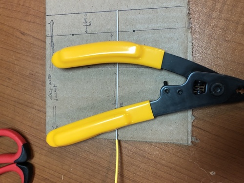
- Stripping the inner jacket of SWS:
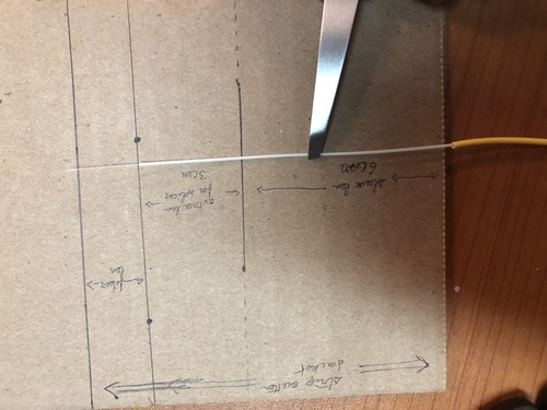
- Positioning the stripped SWS in the cleaver:
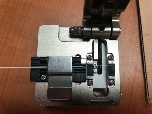
- Positioning the cleaved SWS in the splicer:
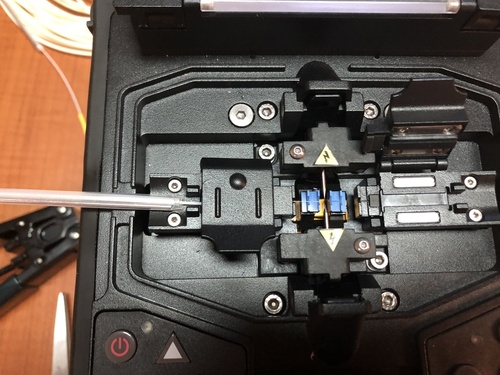
16-17) Stripping the outer and inner jackets of SWOS:
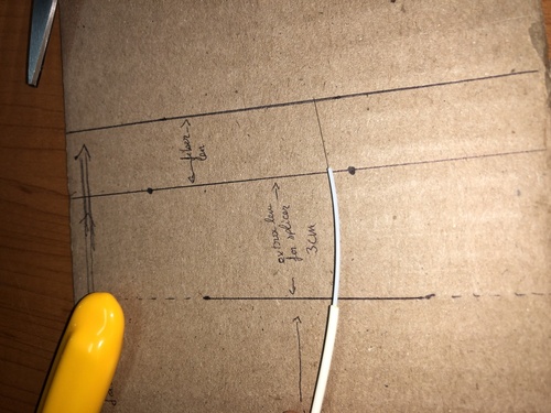
- Positioning the cleaved SWOS in the splicer:
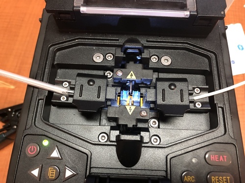
- Read splicer screen to view the quality of the splice and an estimate of signal loss:
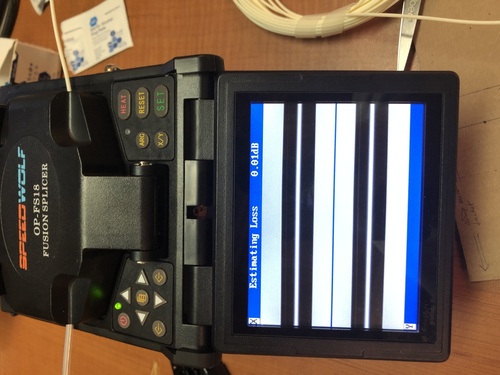
- Test splice:
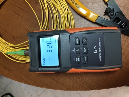
- Place shrink sleeve over the fused, bare fiber and move the whole to the splicer's heating compartment to shrink the sleeve:
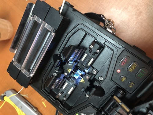
- Verify that the sleeve has in fact shrunk (may need to heat 1-3 times):
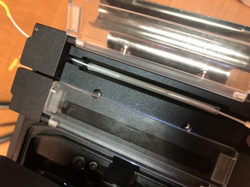
The result:
3. Detailed list of steps
3.1 Prep
-
prepare all the equipment required; includes tools and any PPE.
-
cut shrink tube (20cm).
-
prepare shrink sleeve.
-
mark location to cut on cable from each side.
-
slide shrink tube down either cable.
3.2 Begin Process
-
Take a cable from either side; this cable will be the side with the shrink sleeve (SWS), the other will be the side with out the sleeve (SWOS).
-
Strip outer jacket of SWS (12cm) and cut kevlar.
-
Slide shrink sleeve over inner jacket of SWS.
-
Strip inner jacket of SWS (2cm) into sharps container.
-
Strip cladding of SWS into sharps container and apply alcohol pad.
-
Cleave SWS.
-
Use tweezers to pick up fiber fragment and drop into sharps container; verify that the segment was indeed in the tweezers all the way to the sharps container, and that it fell in the container before putting the tweezers down.
-
Position SWS in fusion splicer.
-
Use tape to clean any potential glass pieces around and between cleaver and sharps container (if they are not moved before cleaving the other side, this can be done after the second cable is cleaved).
-
Take SWOS.
-
Strip outer jacket of SWOS (5cm) and cut kevlar.
-
Strip inner jacket of SWOS (2cm).
-
Strip cladding of SWOS and apply alcohol pad.
-
Cleave SWOS.
-
Use tweezers to pick up fiber fragment and drop into sharps container; verify that the segment was indeed in the tweezer all the way to the sharps container, and that it fell in the container before putting the tweezers down.
-
Clamp SWOS and position it in fusion splicer (clamp to reduce movement when removing the splicer clamp; due to cable curve).
-
Use tape to clean any potential glass pieces around and between cleaver and sharps container.
-
Fuse cables.
-
Connect cable ends to testing devices and test signal loss.
-
Carefully release each cable from splicer clamps.
-
Slide shrink sleeve over exposed fiber and place in splicer's heating compartment; sleeve should cover each side roughly 3cm from joint.
-
Heat 2-3 times.
-
Slide shrink tube over shrunk sleeve; the shrink tube must leave no inner jacket exposed.
-
Shrink shrink tube with lighter while adjusting grip to ensure the shrink tube cools straight; may consider using solder clamps for this step.
3.3 Clean and pack up
-
Use tape to clean each piece of equipment and put them back in toolbox
-
Fold tape in half, sticky side in, to trap any potential glass pieces.
-
Dispose of tape and pack up the rest of equipment.
4. Template
In order to strip jackets quickly and precisely the installer should make a template, such as the one shown bellow.
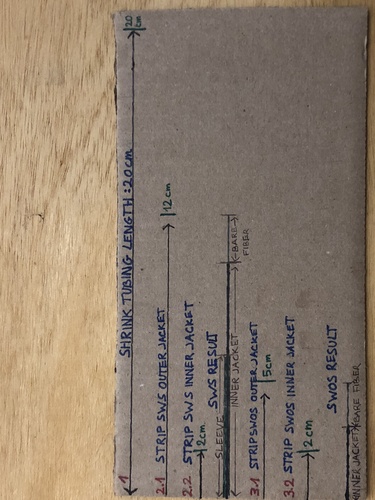
Note that the template in the picture is crowded to illustrate the instructions in section 3; a color coded stick may be easier to work with.
Stick template example (1 dash = 1cm):
< - - - -0- - - - >< -1- >< -2- - >< - - -3- - - - >< - - - -4- - - - >
0: no color -> 8cm; Space for palm of hand.
1: green -> 2cm; Strip inner jacket of both SWS and SWOS.
2: white -> 3cm; green + white = 5cm to strip SWOS outer jacket.
3: yellow -> 7cm; green + white + yellow = 12cm to strip SWS outer jacket.
4: black -> 8cm; green + white + yellow + black = 20cm to cut shrink tubing.
The following pictures show the measurements used to determine the lengths. Note that template lengths are longer to leave ample room for errors.
The pictures show that:
- The outer edges of the cleaver pads are 1.8cm apart; this is the minimum length of bare fiber required for proper grip to cleave.
- The cleaver will leave about 1.5cm of bare fiber on each cable -> the 6cm shrink sleeve will cover about 3cm of bare fiber and 3cm of inner jacket.
- The shrink sleeve on SWS needs to be >4cm away from the splicer needles to clear the clamp (includes 1.5cm of bare fiber) -> 10cm of inner jacket on top of the 1.5cm of bare fiber.
- The resulting gap (shown in the result picture in section 2), from outer jacket to outer jacket, which needs to be wrapped in shrink tubing is about 16cm -> cut 20cm of unshrunk shrink tubing.
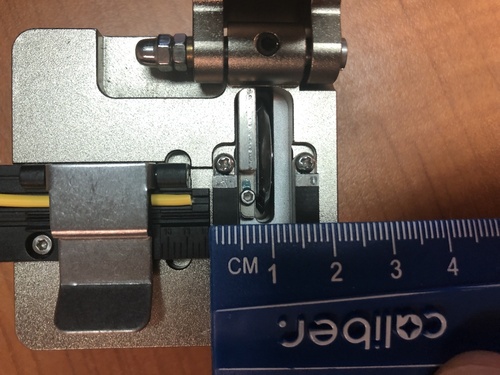
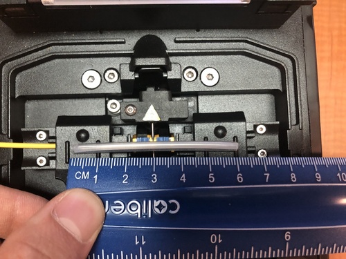
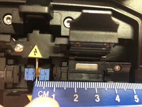
Fiber to the Apartment
The first step is to screw the ONT into the wall in a convenient place using drywall achors. The ONT we are currently using is the Ubiquiti UF-WiFi6-US
Only use white fiber inside apartments, never yellow or any other color. This is to better blend in with the wall. We have custom made 3mm white fiber with termination at one end.
Once the ONT is screwed into the wall, plug in the terminated end of the white fiber. Now you are ready to run the fiber to the exit point (usually above the front door). You first run the fiber down to the top of the baseboard and then along to the nearest corner, attaching it to the wall with silicone or staples. You run the cable up the corner to the ceiling and follow along the corner of the ceiling to the exit point using silicone or staples along the way.
As always with fiber, don't do any hard bends! Let the fiber curve around corners.
There is no loose fiber in the apartment, just a service loop above the door. All the fiber is locked down with silicone or staples the whole way. Any loose fiber will result in service calls. Excess fiber is pulled back into the apartment and left as a service loop above the door. Trim the yellow raceway fiber down before splicing so it one foot from the entry point. Use excess white fiber to enable the splice.
At the exit point you drill a small hole (6mm?) and feed the unterminated end of the fiber through to the raceway. The fiber will be spliced outside of the apartment either with a fusion splicer or with a mechanical splice. The hole must be sealed after you're finished!
The new ONT has a built in router so install it near a power outlet and you are done. You will need to log into the OLT to configure the router
The older model ONT is powered by connecting it to a POE injector, and connecting the data port to a TP-Link/Archer home router.
Support
[to be expanded!]
Fiber support is fairly straightforward. First do the usual test of the wifi router to eliminate that as the problem. Next test the signal going into the ONT by unplugging the connector and connecting it to your meter.
Test db of signal using an OTDR or optical power meter (OPM). The signal should be between -22db to -10db. Less than -24db and the signal is too weak. -8db is the highest limit that will work.
If the signal is outside of the range of -22 to -10 you need to look for where signal loss is occurring. This is typically the splice in the raceway or damaged fiber that has been bent.
Light fiber with red test signal using the OPM or OTDR. This is done from the hallway access box.
Look for loss along the way, especially in the raceway splice. Redo splice if signal loss is there. If the cable is damaged elsewhere, splice around the damage.
Fiber install guidelines
In order to avoid problems with fiber install quality, the following guidelines should be followed:
- Boxes should be located near floor or with long enough winder boxes to enable work on the floor.
- No ladders should be necessary for maintenance/splicing.
- No ladders should be necessary for maintenance/splicing.
- Cable should not be jammed in distribution boxes.
- All cables/ports should be labeled.
- All work should be centrally documented (Mesh or contractors).
- All fibers in a cable should be terminated initially. Never leave fibers unterminated.
Physical Installation
Drilling, Mounting etc
Concrete Drilling
Tips
- Drilling through solid cement walls really sucks. We should probably get contractors to do this rather than doing it ourselves if at all possible.
- There are two sizes of hammer drill bits, SDS-Plus and SDS-Max. The hammer drill we have at the Mesh Room is SDS-Plus, which is the smaller size. This can do up to a 1" bit max it seems.
- SDS-Max drills are expensive, 500$ to buy + ~100$ bit, better to rent if we don't use them often.
- There's rebar inside cinder block walls. If you hit it it's basically impossible to drill through, unless you have a special rebar cutting bit.
- Drill a small (1/4") pilot hole through the wall first. This is basically required to get the hammer drill to not jump around when starting the hole, and it allows you to confirm where you're gonna come through on the other side in case you have to drill from both sides and meet in the middle.
- 2" SDS-Max core drill is the perfect size for the OD of 1 1/2" electrical conduit, which is 1.9" OD
- Stucco outside wall treatment sucks. You can't screw into it, it's basically made of styrofoam.
- Bring a vacuum for dust collection, or a dust mask. Preferably both.
- Clean out holes with canned air / brush.
Non-Penetrating Roof Mounts/Stands
EZ NP-72-200 (Amazon):
| Model: | EZ NP-72-200 |
| Manufacturer: |
Easy-Up |
| Link: |
Amazon Link |
| Price: | 175$ |
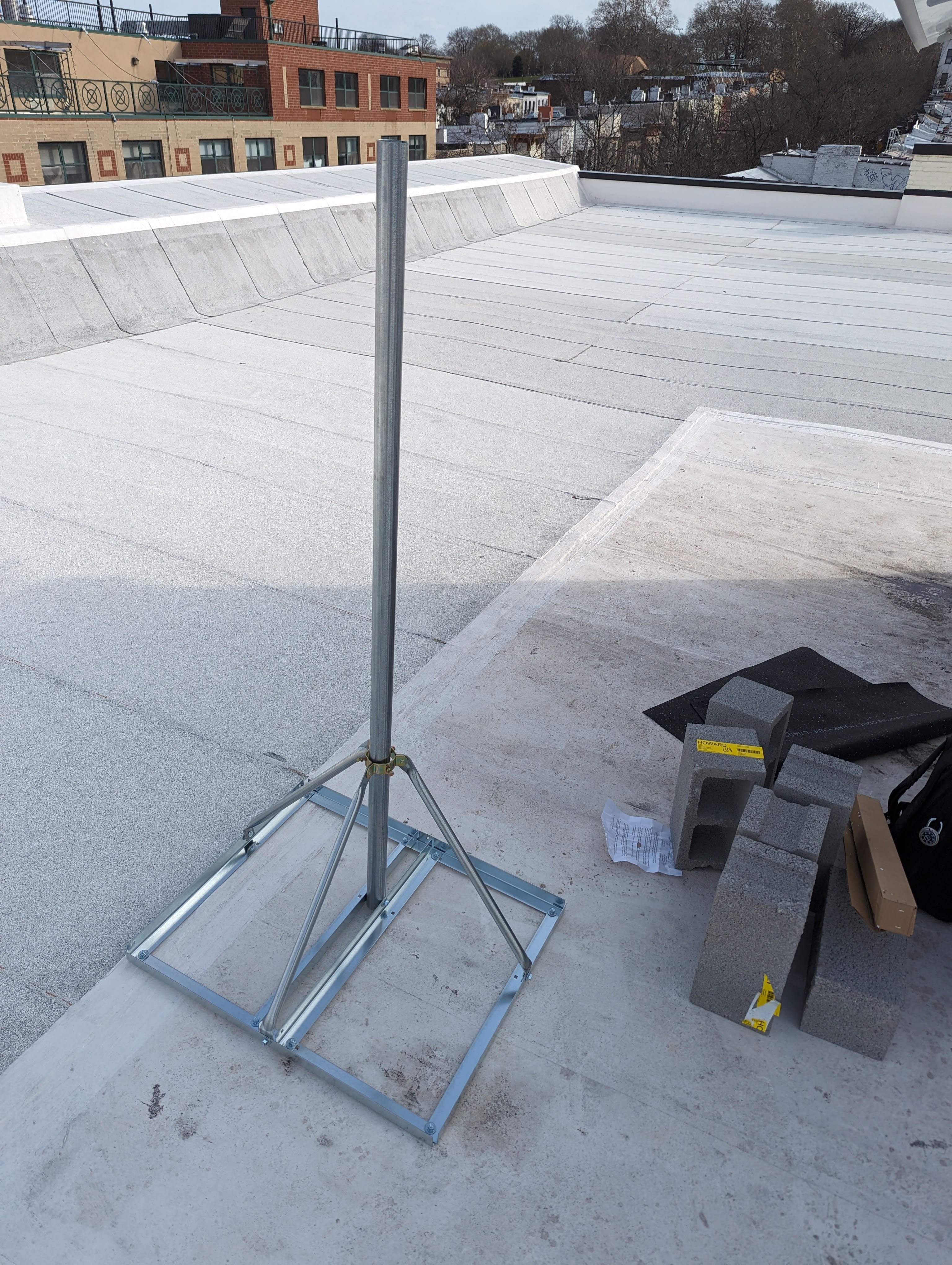
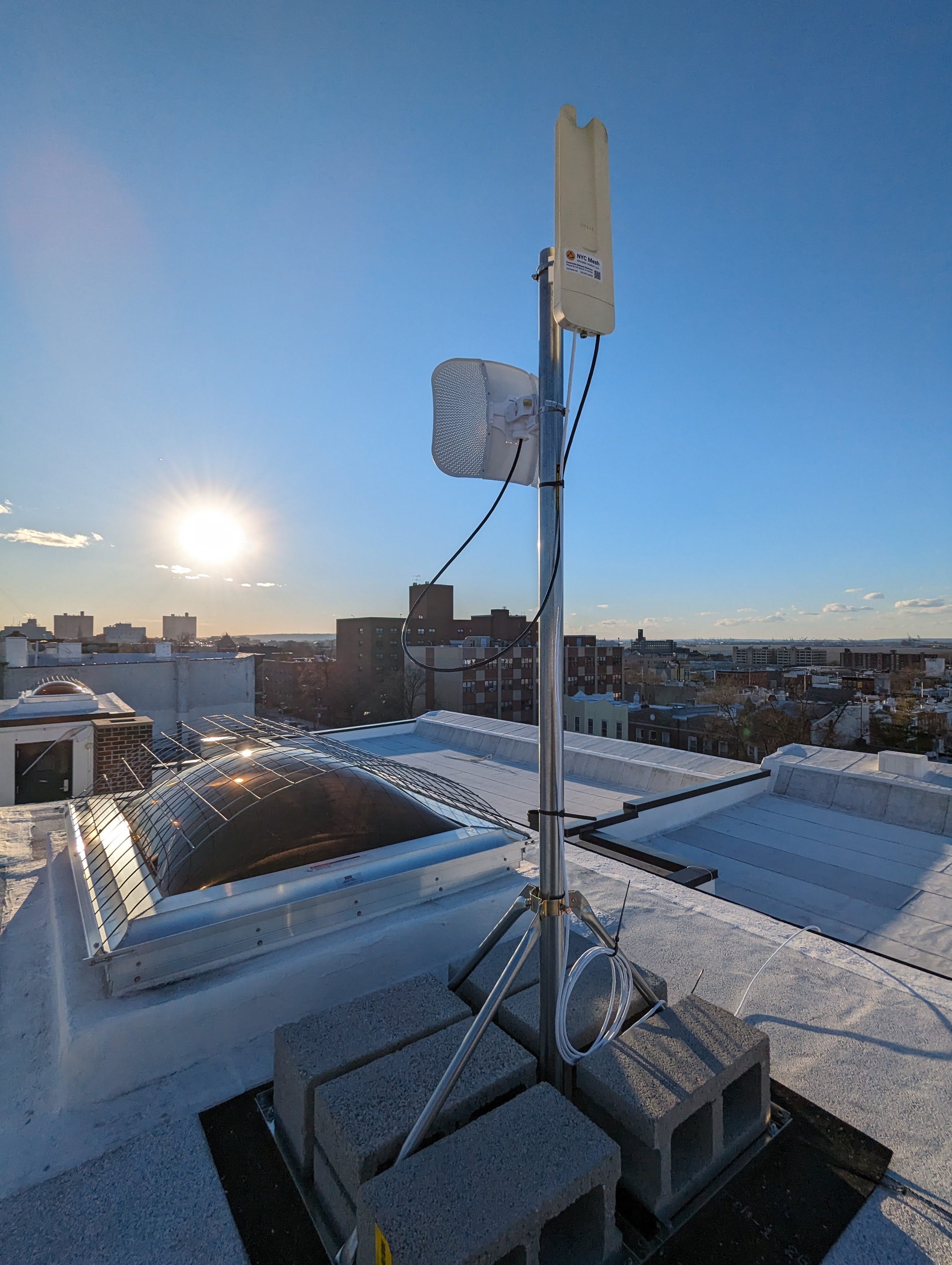
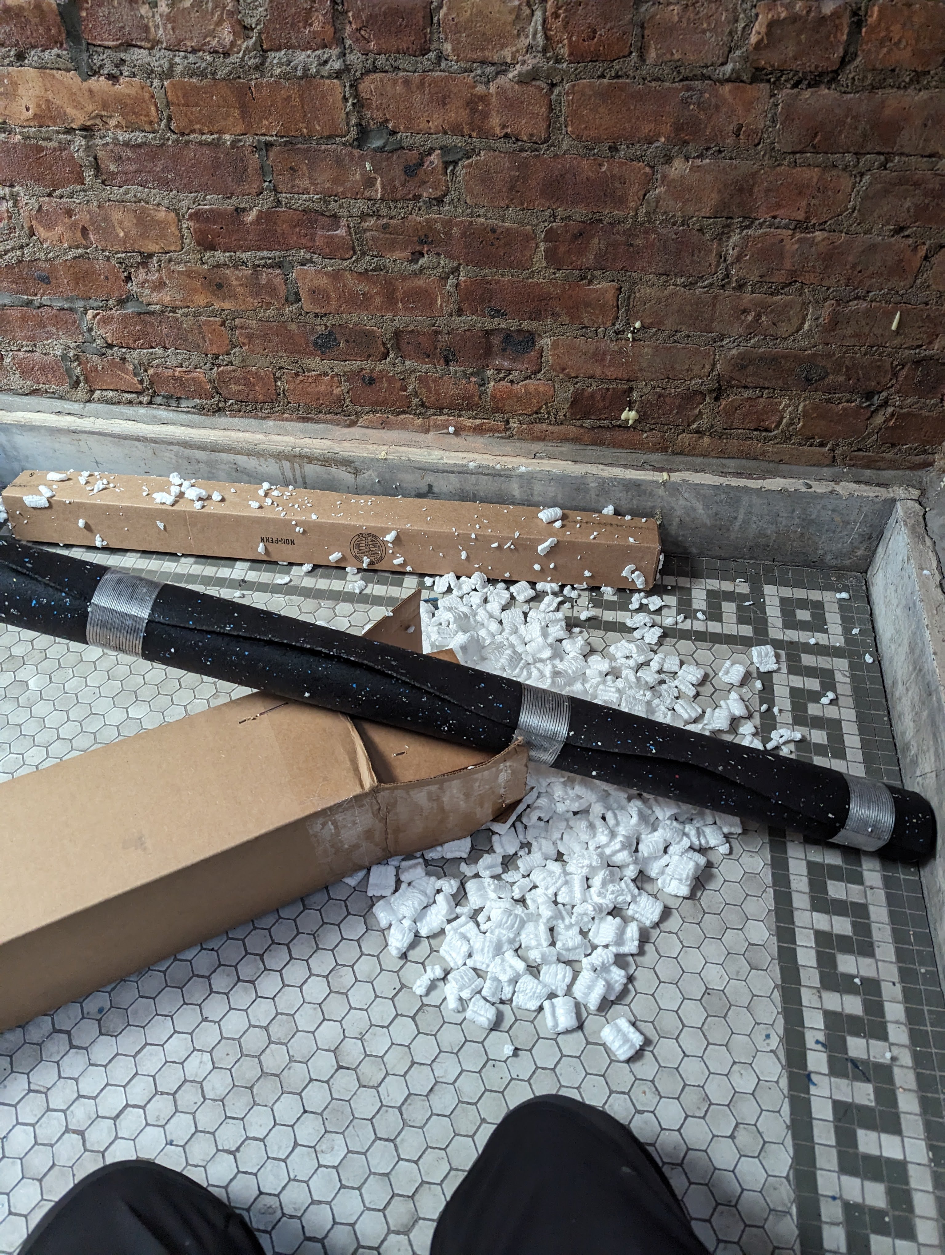
Cheaper stand, includes a mast as well. Feels solid enough for a LiteBeam + Omni, AF60LR, WaveLR or other medium sized antenna. Would probably be reluctant to mount something heavy like a AF24 on it. Maybe mounted low would be fine.
Can hold a max of 8 concrete blocks. (Without stacking them)
Comes with a nice thick recycled (I think) black rubber mat to protect the roof, which is slightly larger than the frame of the stand.
Not the biggest fan of the design. Mast is offset, not centered on the base so there's one direction in which the stand is more likely to topple over. The frame has 3 arms, with a 4 sided base. Should have had 4 arms extending to each corner of the base.
Also whoever decided that filling the box with packing peanuts was a good idea deserves to be fired. Can't open the box on a roof or anywhere windy for fear of packing peanuts going everywhere.
The stand has a collar for mast at the top, but attaches to the bottom of the mast with hole drilled through and a screw. Has some amount of leveling adjustment, but not as much as stands with two collars. Has 3 adjustment bolts per collar.
The mast comes with the tripod and collar parts already assembled, which saves time and confusion. The base is made of angled metal. All screws are the same size, so no worries about mixing them up. Gloves are highly recommended for assembly, lots of sharp metal edges.
Instructions don't have a picture. That would be nice to have.
Wade Antenna NPRM-2:
| Model: | NPRM-2 |
| Manufacturer: |
Wade Antenna |
| Link: |
|
| Price: | 233.50$ (TVAntenna.com) 371.00$ (Anixter previous quote/purchase) |
| Assembly Instructions: |
Link |
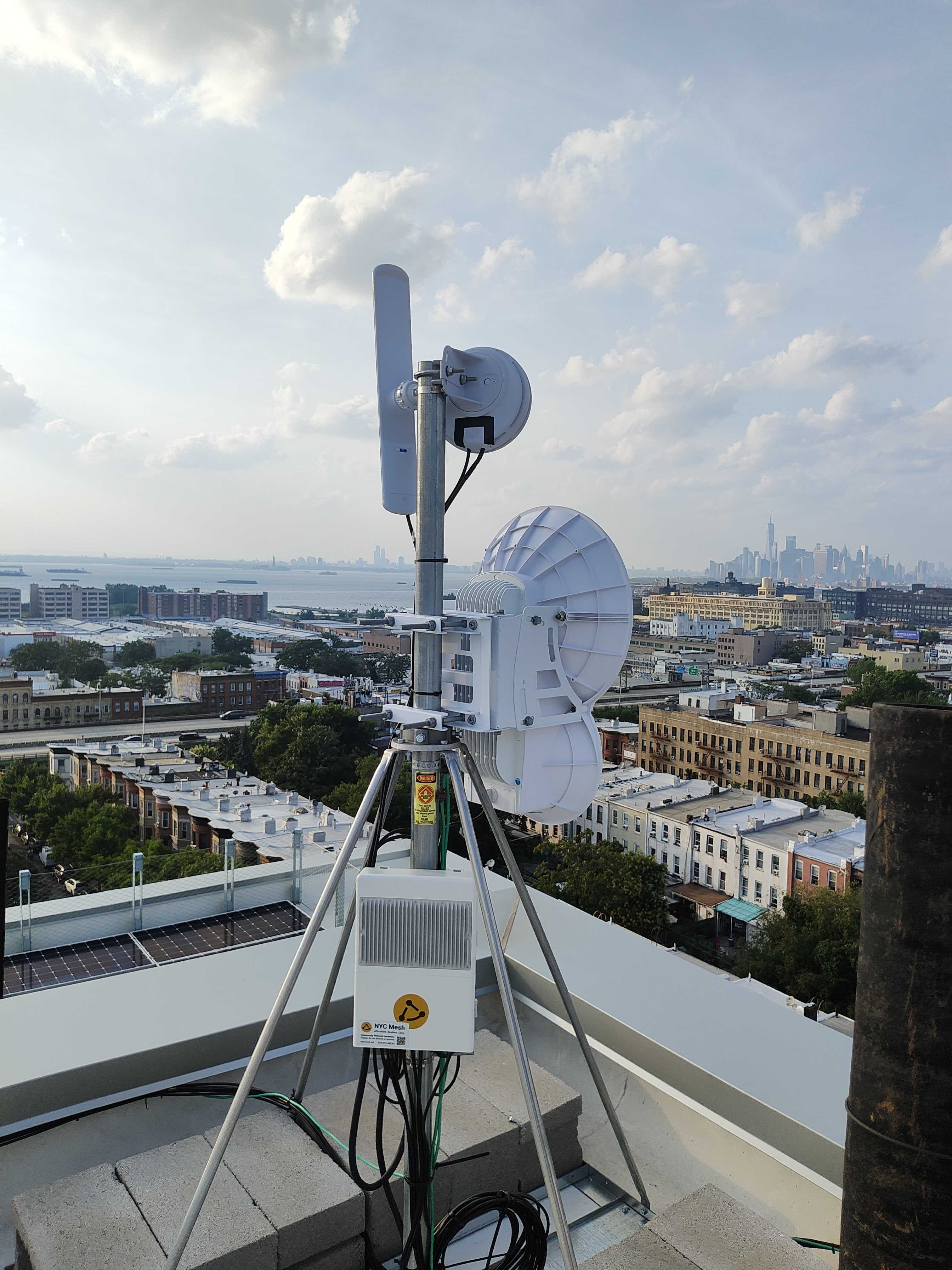
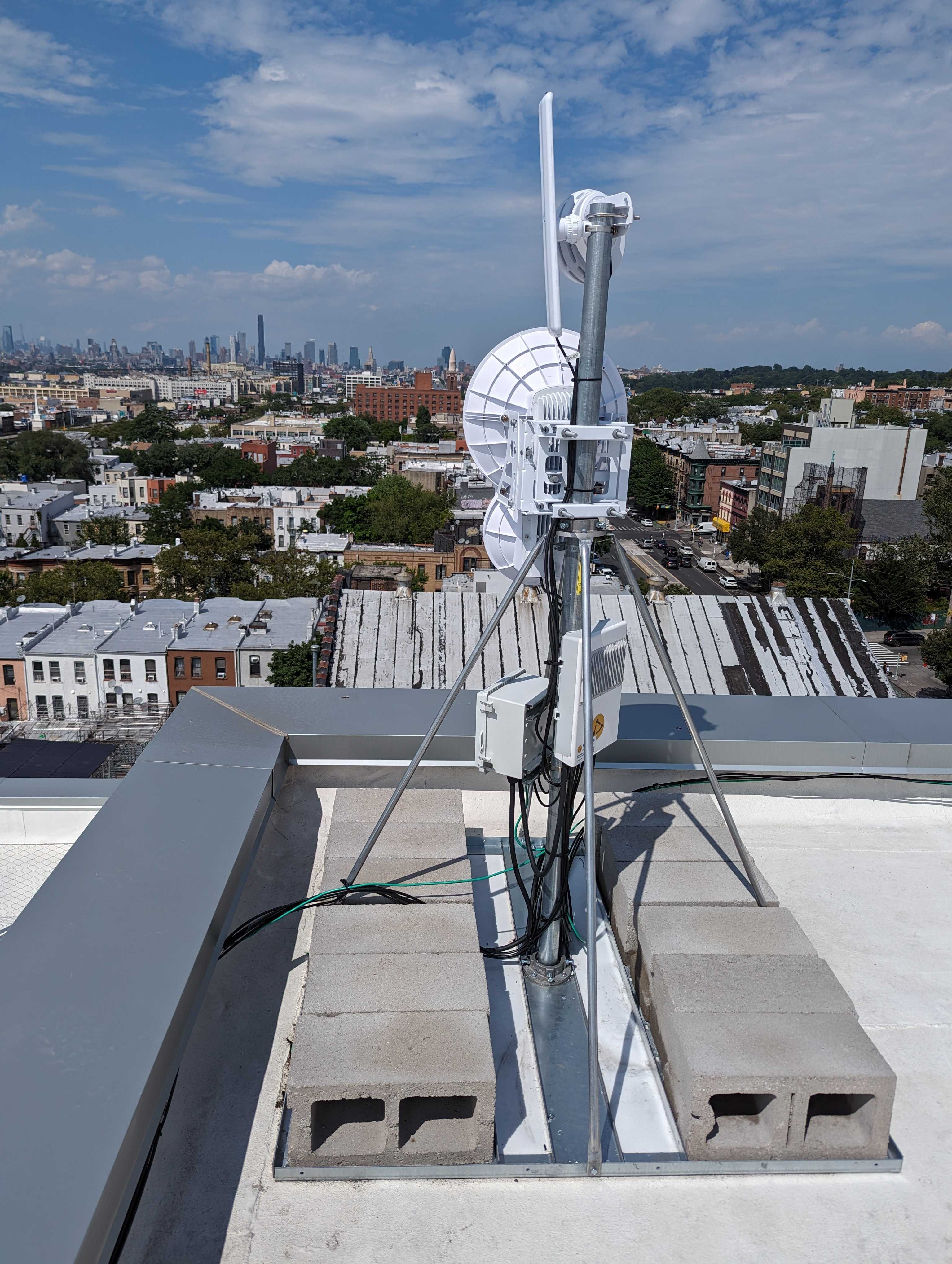
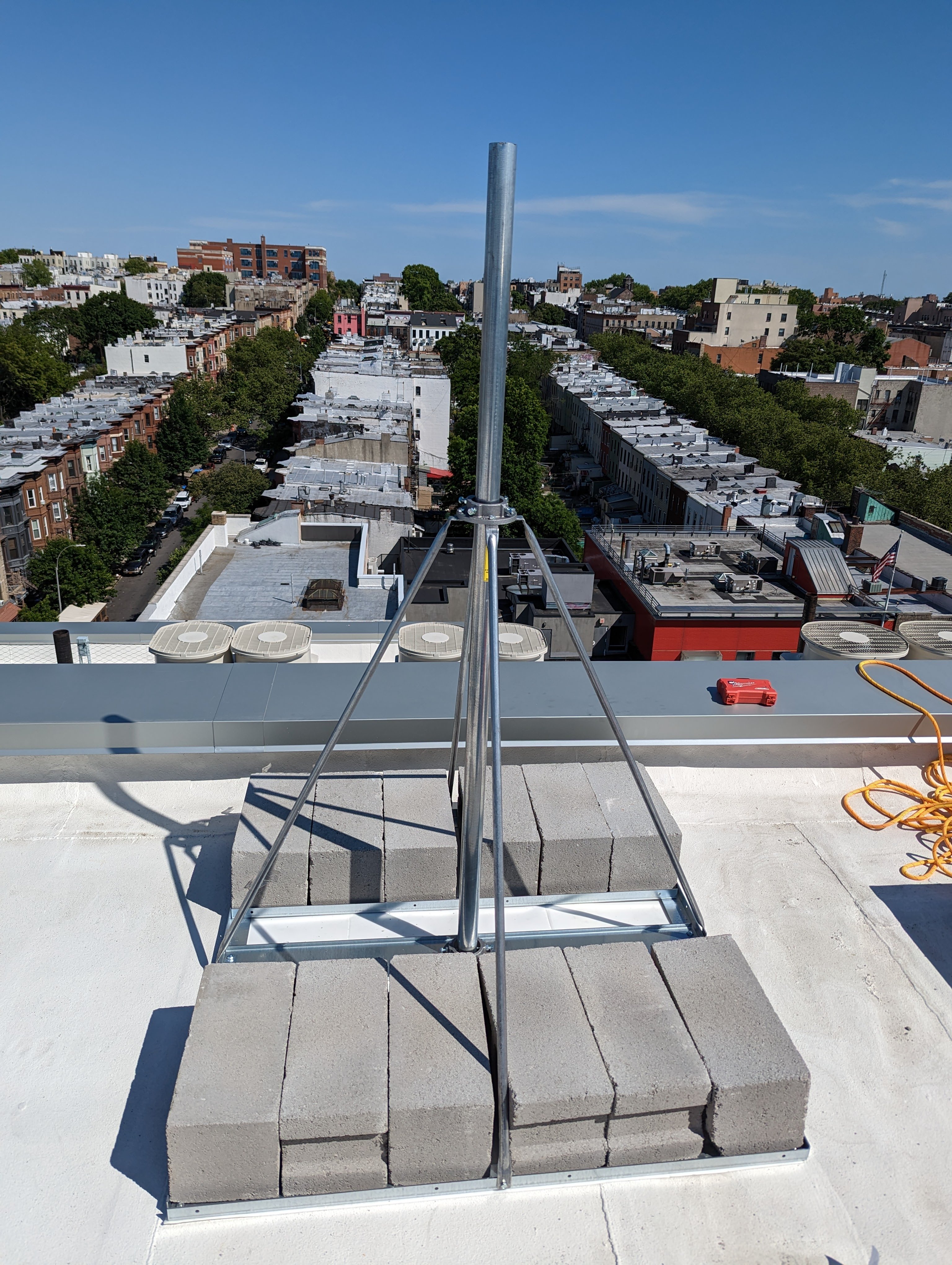
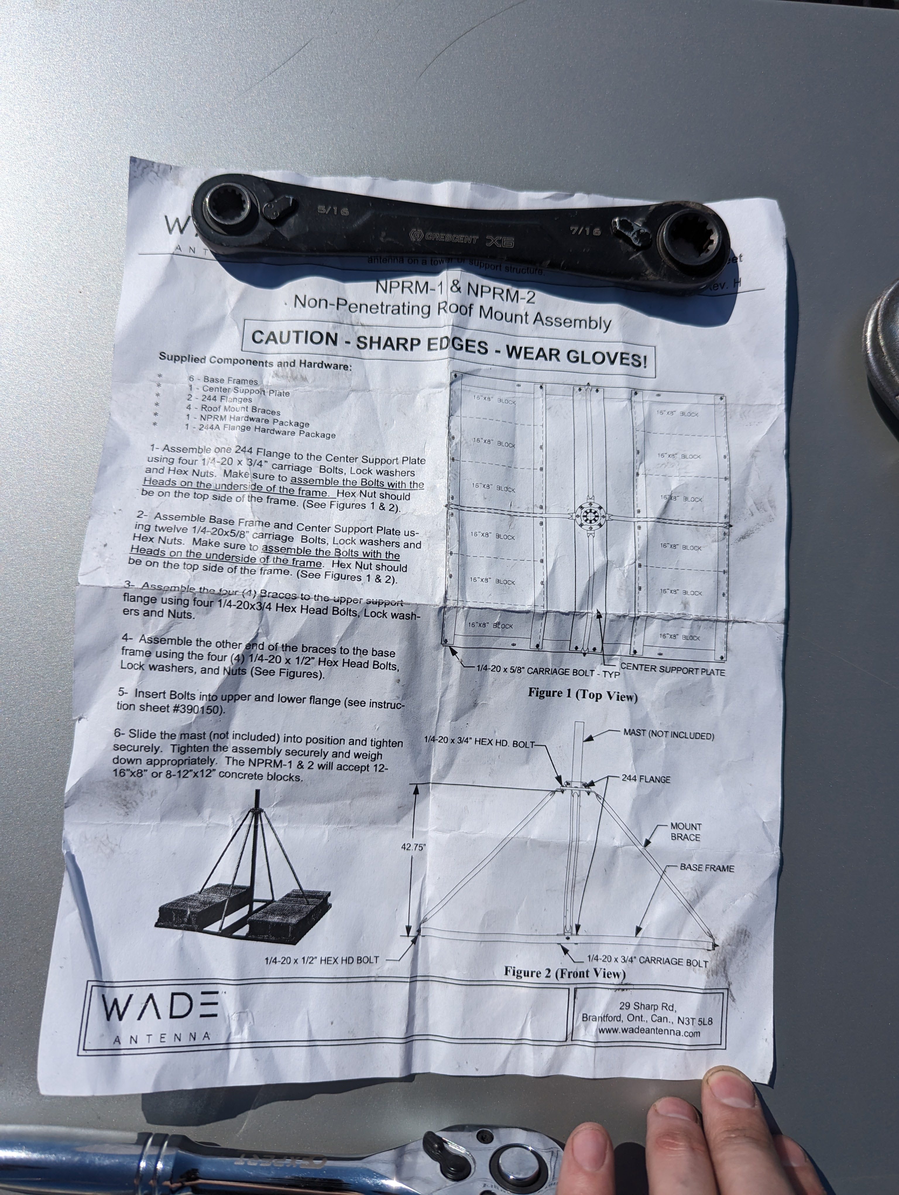
Made in Canada and there's somewhat limited places to purchase it. Last time we purchased from Anixter, but TVAntenna.com seems to have better prices.
Doesn't include a mast.
Can hold 12 concrete blocks max without stacking them, 6 per side.
Used this stand to hold a AF24 + Sectors at Sunset Park Library. Would trust this stand for larger antennas, though would still not mount a Siklu or anything that requires precision alignment. It still has some flex and will probably have issues with alignment on super narrow bandwidth antennas.
Also this stand has wind loading charts from the manufacturer, to plan the amount of concrete blocks required.
Has flanges at the top and bottom to hold the mast. Allows angle adjustment/leveling of the mast by adjusting the 4 bolts on each collar. The bottom flange prevents the bottom of the mast from hitting the roof directly. This stand has 4 arms that extend down from the top flange to the 4 corners of the base.
Assembling this stand can be a little tricky. The instructions are pretty good, though it uses 4 different sizes/lengths of bolts, which are not interchangeable. Need to pay close attention to which bolts should be used where. The bolts are somewhat cheap, we managed to shear one of them during the assembly when we wrenched down too tight. The stand comes completely disassembled.
Getting the arms attached to the upper collar and then lined up with the holes in the frame was somewhat difficult. Had to bend the arms a little bit to get stuff to align as the factory bends were not exactly right. (somehow...)
There is a rubber map (additional 19.50$) which protects the roof under the stand. It's a little thin, white and could be a bit more beefy but it seems to do the job. Not sure how well it's going to hold on in the weather, will need to check back in a year or so. Could probably just buy a recycled rubber sheet of the right size that would be tougher.
Unistrut mounting

Window Drilling Guide
All of our installs usually require getting a cable from the outside to the inside of a building eventually... Drilling through the window frame or lip is the most common way to do this, as it's much easier than drilling through a thick brick wall.
This guide is intended to share knowledge and help familiarize new installers with the types of windows that are common in NYC buildings, along examples of techniques. Many installers find the idea of drilling holes in someone else's house to be daunting, so following along on installs and seeing how other lead installers do it as well it a great supplement to this guide.
Brooklyn Standard Window (Metal Frame):
We call this the Brooklyn Standard Window as it's very common in the pre/post war brownstones around Brooklyn. It can be identified by the large lip on the bottom inside of the window, they are usually metal and usually black. They also usually open at both the top and bottom.
These windows tend to have a lot of play and big tolerances in the bottom sliding pane, meaning that by drilling through the metal lip at the bottom of the window, you can pass the cable through and the window will generally still close and lock.
The metal lip on the bottom can be drilled from both the inside or outside.
<Insert Photo of Brooklyn Standard Window here>
Below is a variation of the Brooklyn Standard Window (that's also white), this time with a piece of wooden trim on the inside. This trim prevents you from drilling from the inside out, without making a big mess of the trim. The track for this situation is drilling a horizontal hole through the metal lip from the outside in, then meeting it with a hole drilled downwards at an angle through the trim.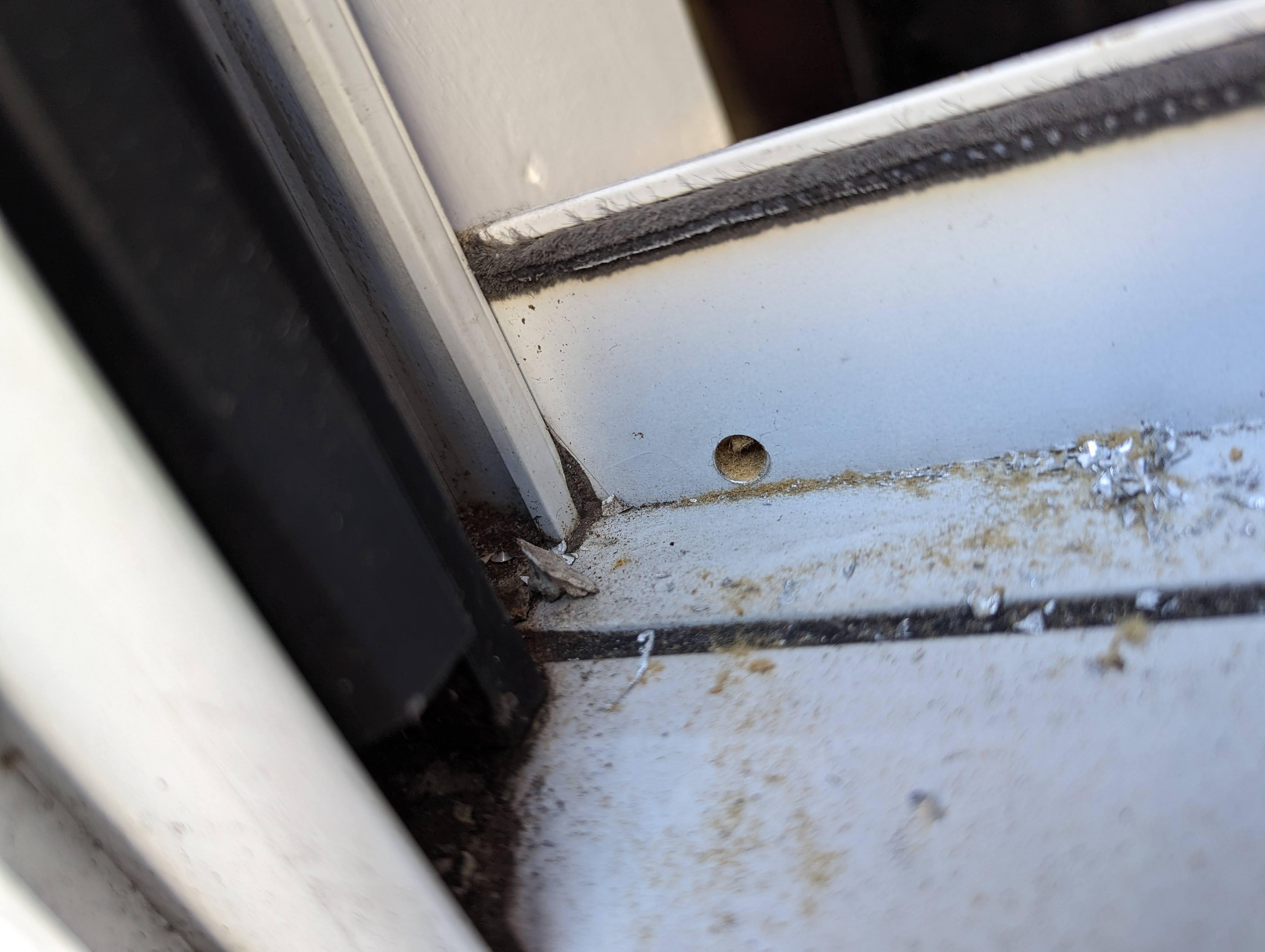
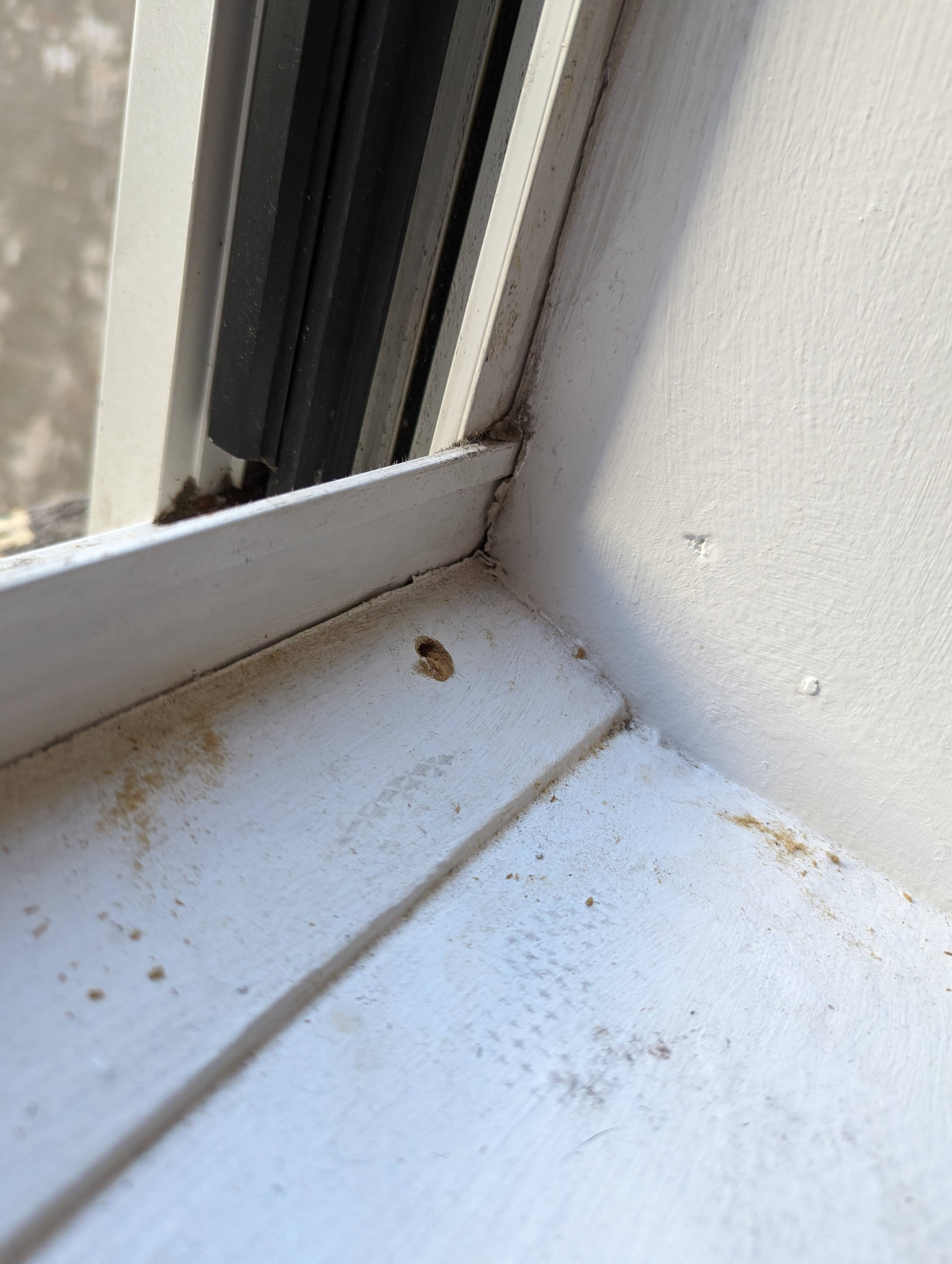
The end result still looks good though, and the hole is drilled low enough in the lip that the window can still close and lock. The holes are caulked shut and the cable is arranged nicely with a cable clip. The member was also informed that they could paint the cable white to match if they wished to do so.
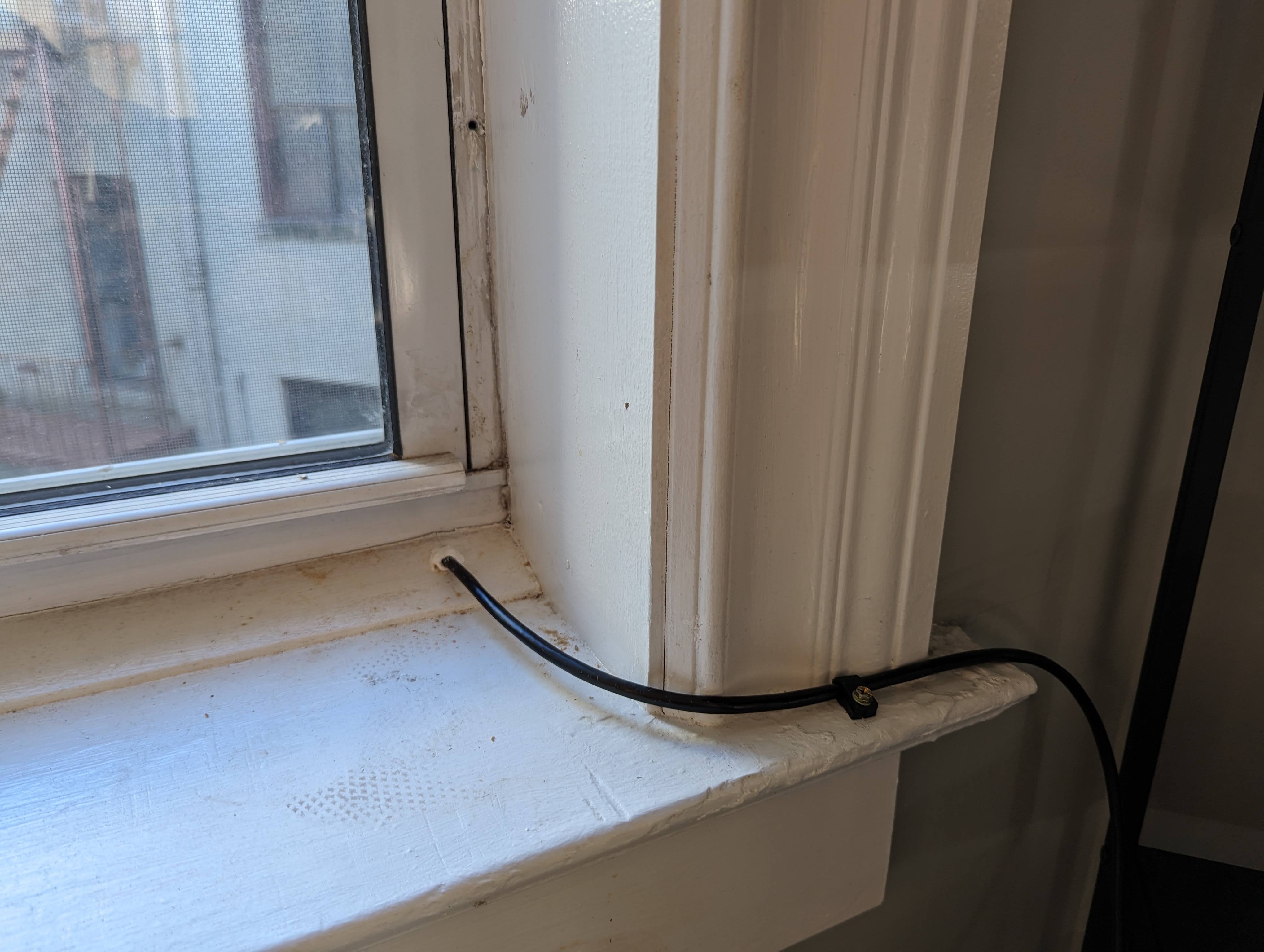
Plastic Frame Windows:
A lot of newer buildings have new plastic framed windows. These windows often have a plastic or wood frame on the inside and sometimes have a metal flashing on the outside. The frames around the sliding pane are also often hollow on both the sides and bottom. (This can be checked by tapping with your hand and listening for a hollow sound)
The plastic frames are easy to drill, so often it's possible to drill the frame around the window, so you don't have to worry about the window closing on the cable. However if you do need to drill the bottom lip you must make sure to drill as low as possible so the cable lies flat on the bottom frame. These windows have much less play to work with, so there's a possibility of it not locking shut once the wire is run though.
Example of a plastic window with a hollow frame. Was able to drill through the bottom frame of the window which is hollow inside.
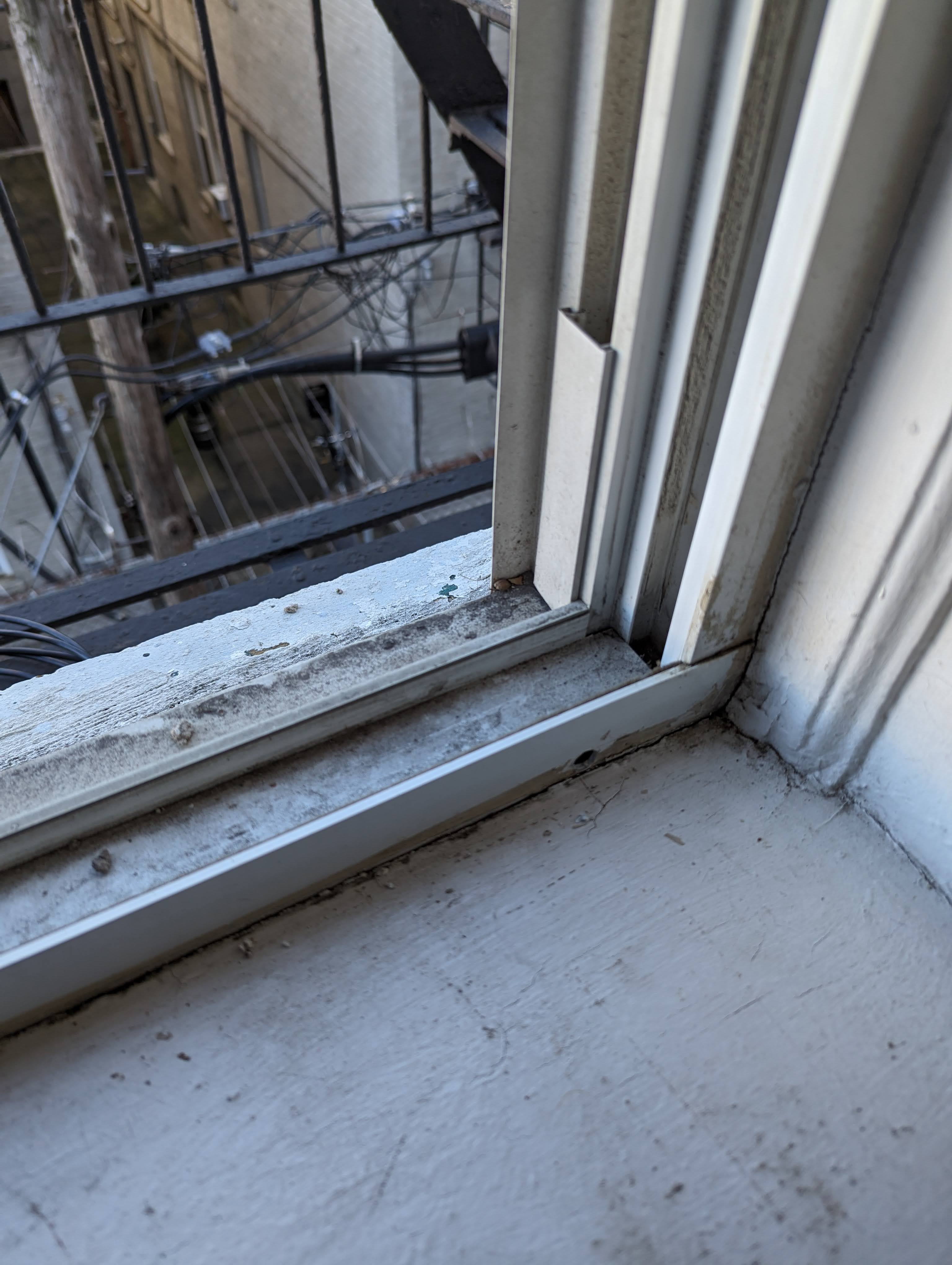
Drilling straight through will the inside hole as low as possible on the bottom frame of the window.
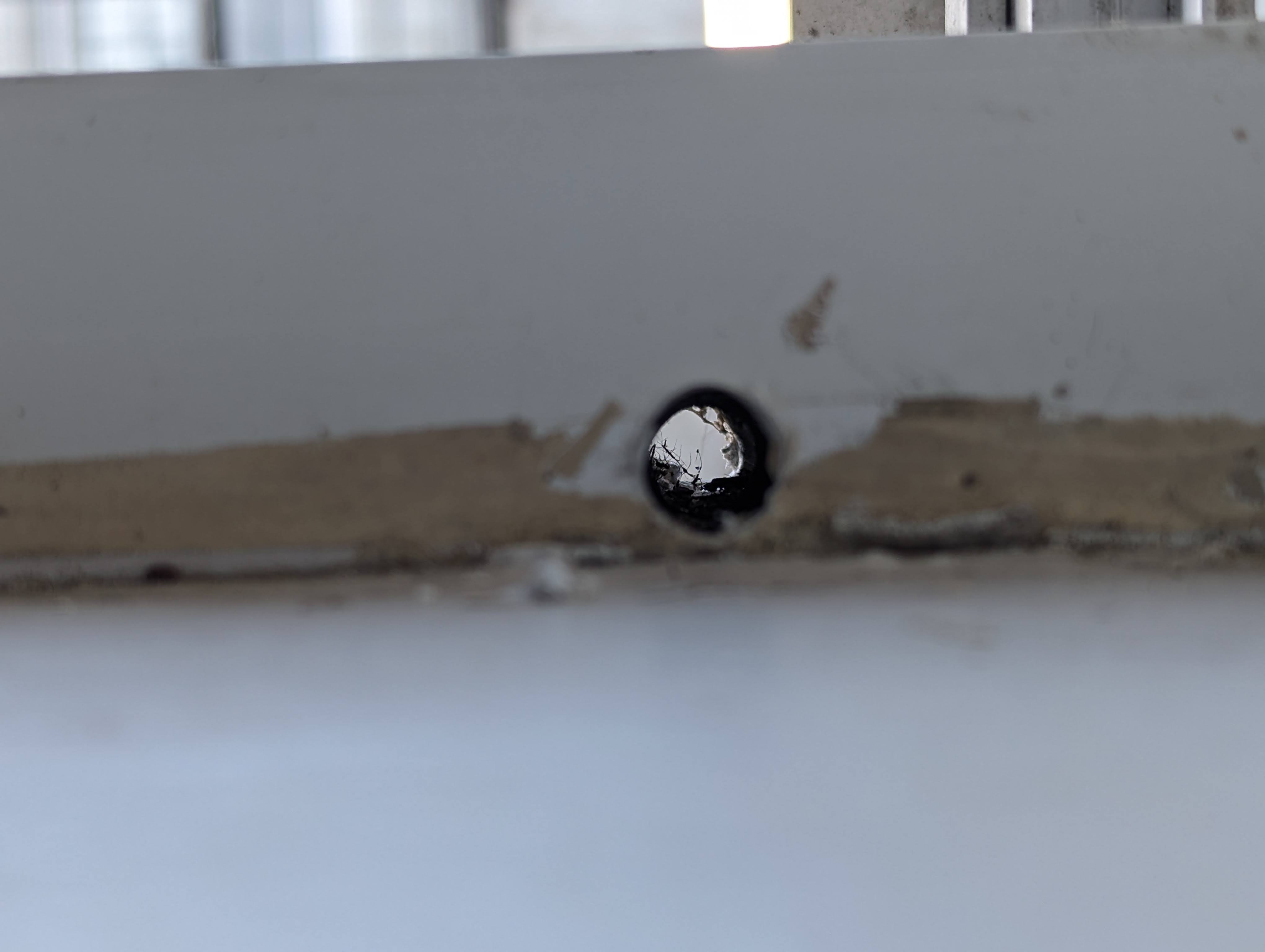
Drill bit existed through existing drainage hole on the outside of the frame, so a bit messy outside hole. Can be sealed with caulk, but as it's an existing (and intentional) drainage hole, it's not necessary. Caulk the inside hole around the cable to prevent cold drafts getting in.
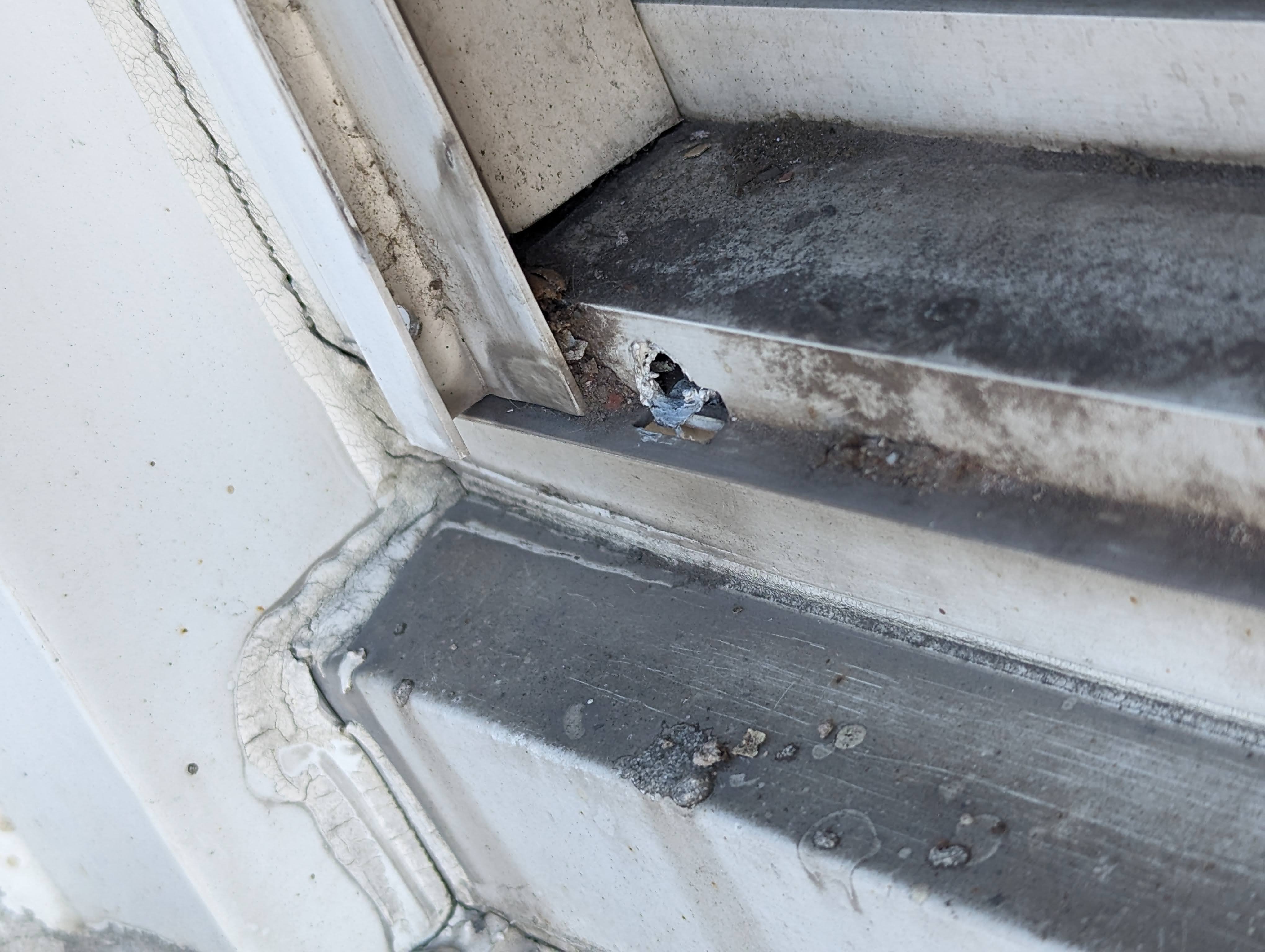
<Insert photos of hole drilled through the side frame of a plastic window>
Side Opening (New fancy windows):
These windows are really problematic due the fact that there are usually very small frames, so there's no where to drill a hole though without impacting the function of the window or being too close to the glass (risk of breaking it).
Most of these windows will also not seal/latch shut properly with anything running through them. You end up with a big gap open around 3 sides of the window which will let in a ton of air and the member probably wont approve of.
In most cases the best way to deal with these new windows is to just find a new point of entry or just drill through the wall.
<insert photo of crappy modern window that's impossible to drill>
Install Planning and Surveys
Surveying and planning installs
Taking Panorama Photos
A direct line of sight to a Supernode or hub node is required to connect to NYC Mesh. To help the install team determine whether a line of sight is possible, we ask new members to provide a panoramic photo of the view from their rooftop. We use these photos to identify an existing hub/node to which your building can connect.
Where to find the panorama photo function on your phone
Most cell phone cameras have panoramic photo capability in camera mode.
iPhone
On iPhones, this feature will be a scrollable option on the bottom of the camera screen.

Android
On Android phones, this feature may be listed under “more” or “...”.

Taking a good panorama image
Rooftop panorama images should show as much of the surrounding skyline and other buildings as possible. We are looking to see if any of our existing hubs or supernodes are visible from your rooftop. For this reason please take your panorama photos from the highest point on the roof if possible (and safe!).
If you are also willing and able, please feel free to annotate cardinal directions (North, South, East, West) and other nearby landmarks (nearby streets, lower Manhattan, midtown, prospect park, etc) This helps our volunteers get their bearings and figure out which direction your photos are looking.
Best practices for roof panoramas
- Show all 360 degrees around your building.
- Take the photos from the highest point on the roof that safe to access if possible.
- If you are aware of any nearby nodes, annotate them on the photo if you can.
- Photos must be clear and well-lit. Take photos around midday if possible on a clear (not raining or foggy) day.
- If taking photos in the afternoon, please avoid glare from the sun and shadows that may obstruct the view.
- Include existing antenna masts or proposed antenna mounting locations if desired.
Best practices for DIY window panoramas
- 180 degree view from the window shown.
- Open window and put your arm all the way out when taking the photos for the best view.
- Show as much of the view out of the window as possible.
- Tilt your phone upwards if necessary to capture the tops of nearby buildings. (If your window is on a lower floor of your building)
- Take photos around midday if possible for the best results. Be aware of glare/shadows from the sun if take photos early or late in the day.
Examples of good panorama photos


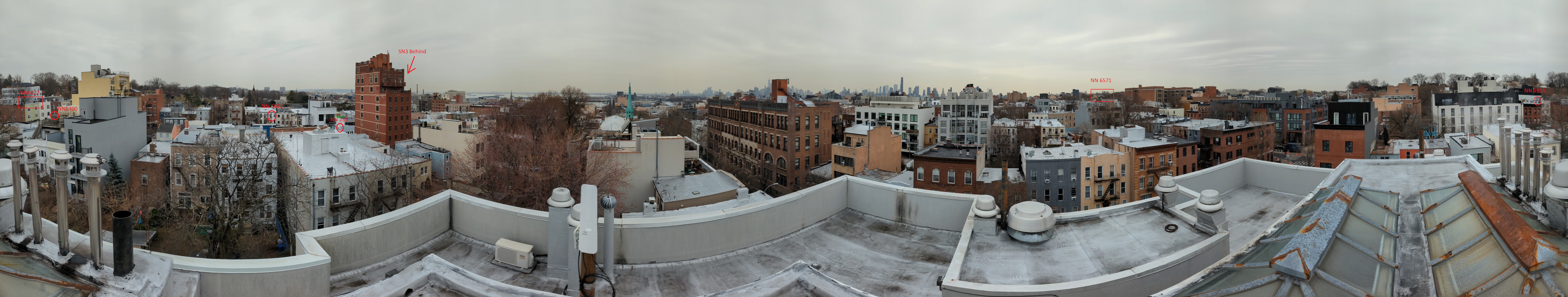
Examples of unusable panorama photos

Photo taken in the evening, too dark. Can't see anything.

Too much glare from the sun. Need to re-take photo closer to midday.

Photo is too low quality, can't see any details. (May need to re-take photo with a better camera or try re-sending as an attachment instead of inserting into the email.)
Surveys
title: "Site surveys"
Site surveys for large buildings help us determine if wireless connection is possible and how we will run cable to apartments. Take photos at each step as you go through the building.
Mounting points on roof
Identify the best mounting points on the roof.
Bandwidth test
Take a battery and do a bandwidth test to the hub or hubs that they are planning to connect to
(This might not be possible if the mounting point is in the water tower)
Conduit or drop point for cable from roof to basement
For large buildings we need to run cable from the roof to the basement. Try to identify existing conduits we can use. We can't use ISP's conduits, unless the building owns them.
Telecom closet access
All large buildings have a telecom closet in the basement. This is one place we might put a panel and run our cables from there.
Raceways into apartments
Hallways often have conduits running where the wall meets the ceiling. This is called a raceway. See if this is owned by the building and we can use that.
Unused wiring that we could use.
Often there is unused or abandoned wiring that we can use. This might be ethernet, coax or even fiber. This will save a huge amount of time and money if we can identify that.
Documentation
When finished, write up a google doc of the survey with embedded photos. We often share these as pdf's with the interested building managers.