OSPF
Open Shortest Path First (OSPF) is a dynamic routing protocol. It uses a link state routing algorithm, thus, it performs functions such as detecting topology changes and link failures. It generally converges quickly and in a loop-free manner. OSPF is often used in corporate networks within a datacenter or building. While OSPF is not generally used as a mesh protocol across a city, it has properties similar to other mesh protocols such as use of link state routing algorithms and auto-convergence.
- NYC Mesh OSPF Routing Methodology
- Rules and Standards
- OSPF Configuration Guide
- Juniper Point-to-Point Guide
NYC Mesh OSPF Routing Methodology
This guide gives an overview of the OSPF methodology and topology currently deployed at NYC Mesh. If you are looking for specific configuration instructions, please refer to the OSPF Configuration Guide page.
Positives and negatives
OSPF is an interesting choice as an in-neighborhood routing protocol because of its ease of setup (auto convergence, no ASNs), and how ubiquitous it is -- nearly every cheap and expensive commercial and open device supports it. These two positives alone make OSPF worth considering.
On the down-side, it is not specifically designed for an adhoc mesh, it trusts blindly, and has very few tuneables. Additionally, there are a few technical challenges such as the lack of link-local address use, only advertising connected networks (not summaries), and some common defaults on various platforms.
Many of these challenges can be overcome by taking some care to make good choices for options when setting up a network.
OSPF Selection
NYC Mesh has chosen to use OSPF as the standard mesh routing protocol of choice. This may be a controversial choice, as _most_ mesh networks in Europe are using custom mesh routing protocols, or encrypted routing protocols. We have chosen this path because:
- OSPF is an open-standard with implementations on many platforms, open and closed, including cheap older professional switches
- OSPF hugely reduces the burden for installers and members to maintain the network
- OSPF cooperates well with other protocols such as BGP
- Other Mesh networks (CTWUG in South Africa for example) have scaled OSPF to 1000+ routers.
NYC Mesh utilizes a wide range of hardware with differing capacities and weather resiliency characteristics. Being volunteer-driven and operated, it's important that the network be resilient, but also easy to maintain and scale. OSPFv2 Point-to-Multipoint allows us to modify routing tables and plan for expansion without overly-complicated configuration planning.
Important Note: making changes to default OSPF costs can have unintended effects, up to and including network-wide outages, and frequently requires modifying Hub configurations. Testing and learning should not be done in production environments. Before making changes to NYC Mesh routing configurations, discuss in our Slack #architecture channel and/or applicable hub channel and check the NYC Mesh Node Explorer tool for current routing information.
Designing the basic architecture
To standardize across the network, each router has a Mesh Bridge Interface on the OSPF Area with default cost of 10 to all adjacent neighbors. This ensures symmetry in link costs on both ends of the link, keeping bi-directional traffic following the same path. For each "hop" to an internet exit, each router incurs its link cost to transit to the next hop. By calculating the lowest cost to an internet exit, the local router sends its traffic on an Internet exit in (usually) the most efficient manner, automatically.
Example: Node path to internet exit with all default costs
Node A > 10 > Hub > 10 > Supernode > 1 > Public Internet
In the above example, the Node incurs cost 10+10+1=21 to exit to the Public Internet. Unless a lower cost exit becomes available, this will be the preferred route for all internet traffic to and from Node A.
Now that we've standardized route costs, we need to design priority and redundancy to take advantage of nodes clustered around each other while preferring higher-capacity links.
The WDS bridge: ensuring Hub-and-spoke routes are preferred over WDS routes
NYC Mesh uses Omnitik wireless routers at almost all member nodes to automatically connect to each other, providing numerous backup routes in case of hardware failure or network changes, but these connections are often slower and less reliable than point-to-point and point-to-multipoint connections in our Hub-and-Spoke model. To account for this, we put the Omnitik<>Omnitik WDS links on a separate "WDS Bridge" on every Omnitik router with default cost of 100.
Example: Node preferring Mesh Bridge over "shorter" WDS links
Node A > 100 (WDS) > Node B > 10 > Supernode X > 1 > Public Internet
Node A > 10 > Microhub > 10 > Hub > 10 > Supernode Y > 1 > Public Internet
In this example, Node A prefers to exit via Supernode Y as the cost it incurs is 10+10+10+1=31, versus 100+10+1=111 via Supernode X. If we did not have higher WDS costs, Node A would instead prefer the shorter link to Supernode X, but would very likely experience poorer performance.
For more details on the hybrid Hub-and-Spoke + Mesh model we deploy, see the Mesh page.
Example: Prospect Lefferts Garden
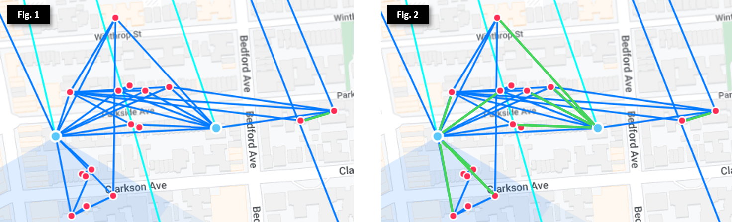
In Figure 1, we see many nodes (marked as red dots) clustered around 2 Microhubs (marked as blue dots) in Prospect Lefferts Garden, as well as multiple exit routes to the north. While most of the nodes will automatically find the best exit, there are some that may have equal costs through multiple exits. To mitigate this, we set preferred routes (via hardware like SXTs, or software with virtual wireless interfaces) on the Mesh Bridge, as illustrated by the green lines in Figure 2. This ensures each node selects its fastest and most stable route to send and receive internet traffic.
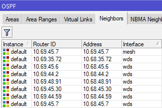
We can see this in action on the Omnitik: 10.69.45.7 is on the the "Mesh" bridge interface, meaning it incurs cost 10 to transit. All other adjacent routers are on the "WDS" bridge interface, and incur cost 100 to transit. This setup ensures the local node prefers the 4507 Microhub as its exit route, but also has backup routes in case 4507 goes offline or one of its upstream links is broken.
By implementing this architecture across all routers on the network, we now have high resiliency to outages, scalability, and minimal configuration effort.
Bridge Filters
Before we go further, its important to mention bridge filters. These are required to make OSPF work properly and also ensure members within the same building are isolated from each other. There are 3 filters applied to standard Omnitik configurations.
[admin@nycmesh-xxxx-omni] > interface bridge filter print
Flags: X - disabled, I - invalid, D - dynamic
0 chain=forward action=drop in-bridge=mesh log=no log-prefix=""
1 chain=forward action=drop in-bridge=wds
2 chain=forward action=drop in-interface=wlan2 - Filter 0 prevents devices on the Mesh Bridge from directly interfacing with each other. Disabling or deleting this filter allows traffic to move freely across devices on the Mesh Bridge without first traversing the OSPF Area and incurring the OSPF cost of 10 before moving to the next router in the exit route.
- Filter 1 functions the same as Filter 0, but applied to the WDS bridge
- Filter 2 ensures that guests connected to the open -NYC Mesh Community Wifi- SSID are isolated from each other
- Note that routers without built-in wireless access points, including "core" routers within NYC Mesh, only require Filter 0
It is critically important to ensure these filters stay enabled on each router to ensure individual routers don't "bridge" connected nodes and Hubs, leading to unintended routing paths. Further explanation and examples of bridging scenarios are covered below.
Sidebar: The case against OSPF automation and summarization
Given the scale of the problem and continued growth, we must consider an important question: why not implement automation to dynamically adjust OSPF costs based on link quality, and/or utilize summarization and redistribution to simplify planning?
As mentioned above, our network design is meant in part to balance the following three goals:
- Resiliency across a widely distributed network in a dense urban environment
- Simplicity of configuration and maintenance by a 100% volunteer team of architects, engineers, coders and enthusiasts
- Scalability for future expansion
Further, NYC Mesh has no CEO, directors, or employees, and the board intentionally does not have decision-making authority over non-financial/legal matters; as documented in the NYC Mesh Commons License, the design, planning, maintenance and support of NYC Mesh is done solely by community members and volunteers. While we do have highly-skilled volunteer network engineers, the day-to-day maintenance and monitoring of the network is done by members with varied skill levels; we generally prefer easy-to-maintain solutions over highly customized configurations requiring extensive knowledge and training.
Finally, as we primarily rely on member donations to maintain and expand the network, we generally avoid high-end enterprise-grade hardware or software requiring recurring subscription fees and support contracts to minimize operational expenses. As NYC Mesh continues to grow, we may need to adopt more robust and dynamic routing and load-balancing techniques, and will look to our community to collectively decide on the path forward.
Scaling out the Hub-and-Spoke model
This baseline architecture works great in individual neighborhoods and on relatively linear routes, but with over a thousand nodes connecting to 60+ Hubs with links crisscrossing New York City, some planning and manual intervention is required to ensure stability and speed for all connected members.
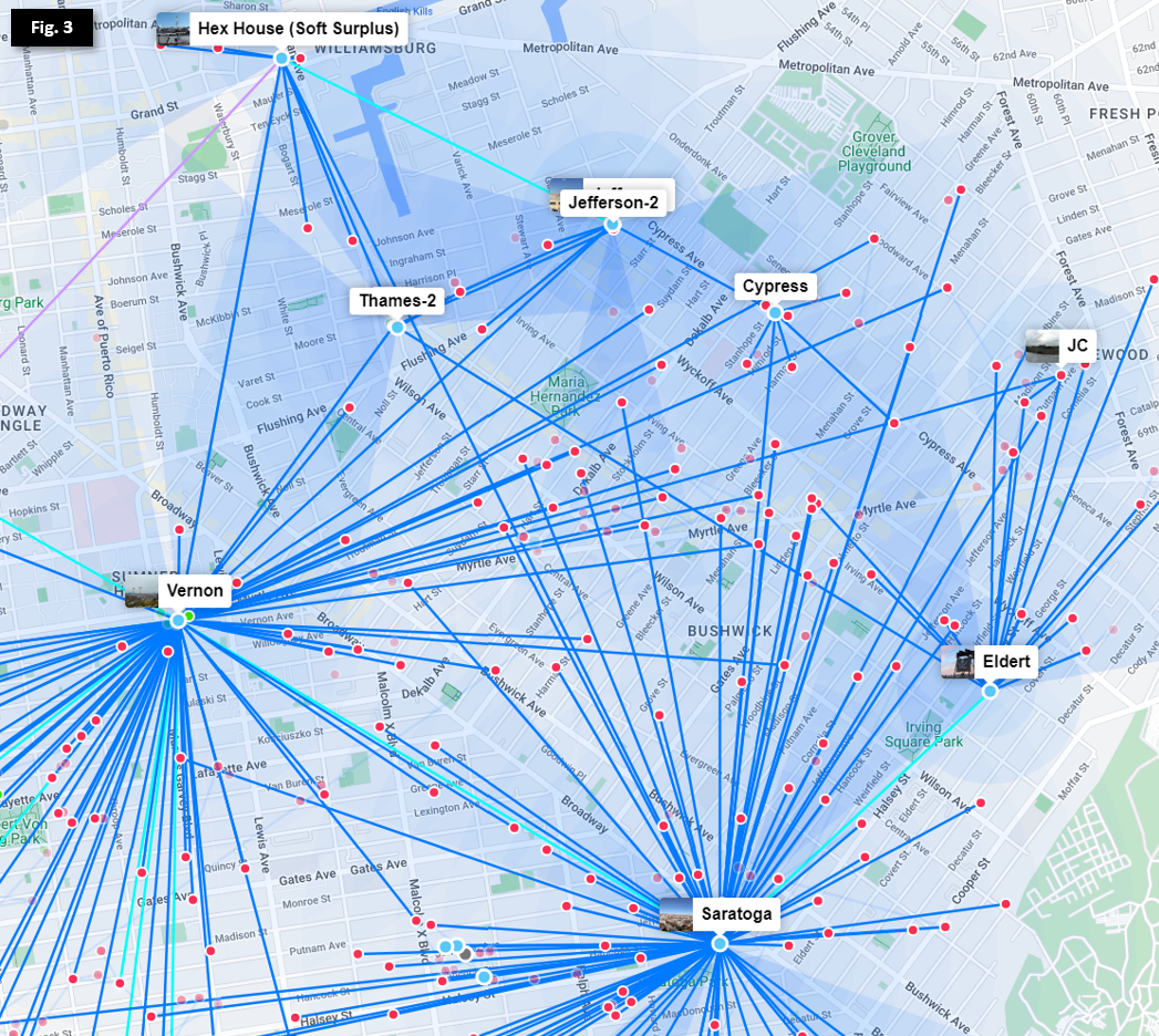
In the Bed-Stuy, Bushwick, Ridgewood, and Crown Heights neighborhoods show above in Figure 3, we have over a dozen Hubs serving hundreds of members. Efficient routing and redundancy across multiple wireless links requires further options for route cost between 10 and 100.
In efforts to minimize single points of failure in our network (hubs having only 1 exit route) and provide dedicated backup routes in cases of weather impacting high-frequency links, we deploy redundant links in a "triangle schema" so that each hub has multiple low-cost routes to exit. To see this deployed, let's remove the nodes from the above photo and focus on the Hubs.
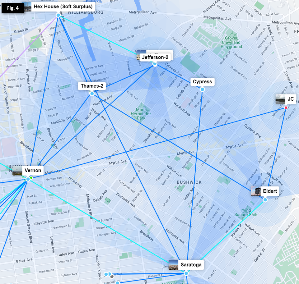
As we can see in Figure 4, most Hubs have 2 or more exit routes so that an outage of an individual link or Hub will not isolate any other Hub. Additional routes leading off Figure 4 allow multiple exits from both Vernon and Hex House, as well as other lower-capacity links through smaller Microhubs and nodes.
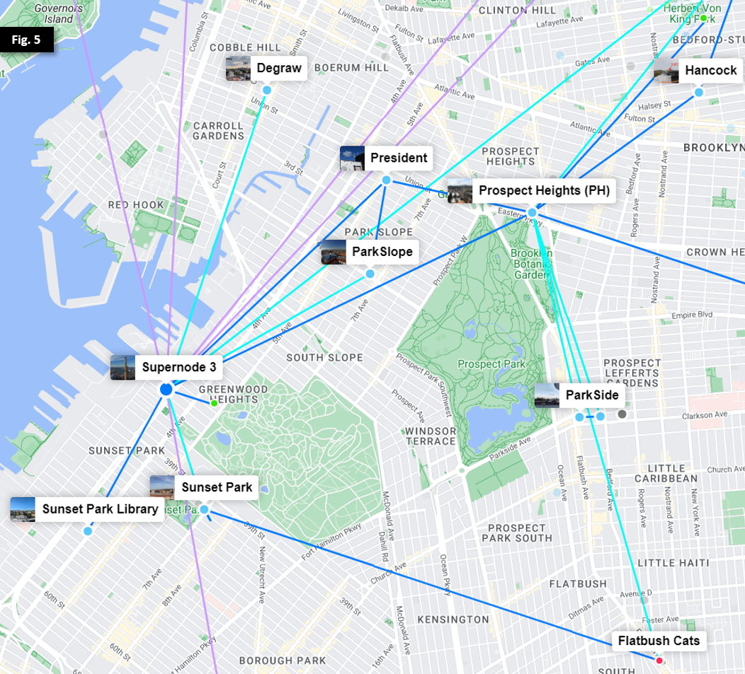
In Figure 5, we observe a similar trend as we move southwest towards Prospect Park and Supernode 3 at Industry City.
Load-balancing across varied hardware
NYC Mesh uses a broad range of purchased and donated Ubiquiti and Mikrotik hardware with varying capacity, capabilities, and rain fade resilience, and members are allowed to extend the network at will pursuant to the Network Commons License. Because our OSPF link costs are static and do not automatically increase or decrease based on link quality, limiting ourselves to just two options for link cost will quickly cause issues as the network grows. Here are just a few use cases to consider:
- Avoiding unintentional bridging of Hubs with low-capacity connections as members join and add equipment and links
- Intentional design of secondary and tertiary routes for major Hubs to mitigate rain fade and hardware failure
- Multi-antenna routes with differing performance characteristics (primarily high-capacity 60GHz links with dedicated 5GHz backup hardware)
- Minimizing impacts from misconfigured DIY and new infrastructure installations
To meet these goals, we need to set up custom link costs on backup routes as well as between high-traffic Hubs.
Example: Microhubs between Major Hubs
Our Vernon and Prospect Heights Hubs collectively carry more than 80% of NYC Mesh network traffic in Brooklyn. By design, each Hub's primary exit is through different Supernodes to the public Internet (Vernon through Supernode 10 in Manhattan, and Prospect Heights through Supernode 3 in Industry City). To allow redundancy between their exits, a dedicated 60GHz link (in teal) is deployed between the two, but Vernon and Prospect Heights also have more preferrable secondary links (illustrated further below in Figure 7). This requires the link to have a slightly higher cost (in this case, 15) so that each Hub prefers other backup routes in case of primary exit link outages.
To make matters more complicated, Microhubs in between Vernon and Prospect Heights connect to both Hubs to provide their own redundancy, as illustrated in Figure 6.
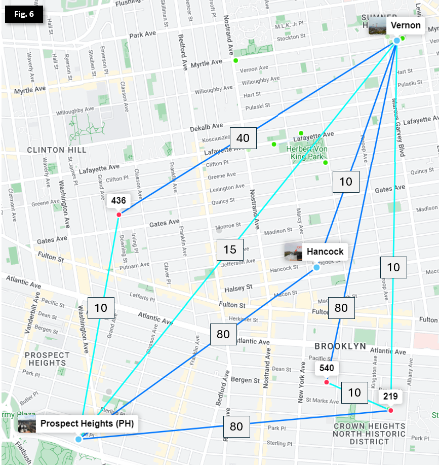 Note: nodes and sector coverage have been omitted
To ensure each Microhub prefers the fastest route and they don't bridge Vernon and Prospect Heights by having additive link costs lower than the Vernon <> Prospect Heights 60GHz link, we need to manually set the backup links with higher costs.
Reminder: before setting up secondary links, double-check that the appropriate Bridge Filters are enabled on the local router. A misconfigured or disabled Mesh Bridge Filter will result in 0-cost links between neighboring nodes and Hubs, risking major network congestion or outages.
- 436
- Primary: Prospect Heights via AF60LR PtMP (default 10 on Mesh Bridge)
- Secondary: Vernon via Litebeam 5ac PtMP (manual 40 on OSPF area)
- Hancock 3607
- Primary: Vernon via Litebeam 5ac PtP (default 10 on Mesh Bridge)
- Secondary: Prospect Heights via Litebeam LR PtMP (manual 80 on OSPF area)
- St Marks 219
- Primary: Vernon via AF60LR PtMP (default 10 on Mesh Bridge)
- Seconday: Prospect Heights via Litebeam LR PtMP (manual 80 on OSPF area)
- 540
- Primary: St Marks 219 via LHG60 PtMP (default 10 on Mesh Bridge)
- Secondary: Vernon via Litebeam 5ac PtMP (manual 80 on OSPF area)
Determining link costs
Note that there is no firm methodology or formula for calculating optimal custom link costs in this model, though backup links are generally set between 20 and 80 depending on upstream impacts. Sufficient buffer should be allocated between primary and secondary routes to allow expansion and updates with minimal changes required to upstream OSPF costs or routes.
The NYC Mesh Node Explorer tool generates live and historical mappings of nodes and link costs, allowing us to quickly determine primary exit routes and costs, as well as an outage simulator tool that is extremely helpful in validating configuration of secondary routes.
You can also determine current exit cost of any Mikrotik router running RouterOS v6 with the following command:
[admin@nycmesh-xxxx-core] > routing ospf route print where dst-address =0.0.0.0/0
# DST-ADDRESS STATE COST GATEWAY INTERFACE
0 0.0.0.0/0 ext-1 20 10.70.253.xx bond1.1010 Note: identifying information has been removed from this terminal export
When selecting a custom link cost that may bridge segments of the network, the following factors should be taken into account:
- What is the preferred exit path for the local router?
- This will normally be the link with the highest capacity (60 GHz), and will usually have default cost 10 on the Mesh Bridge to keep configuration simple
- Will the backup link connect to the same Hub as the primary, or a different one?
- When the primary and secondary/backup links connect to the same upstream Hub, it's generally safe to set the backup link to cost 20 without further impacts
- What are the current primary and secondary exit routes & costs for each upstream Hub?
- This gives us an understanding of where traffic will route along each hop of the network
- In the event of a primary link failing on an upstream Hub, will the new bridged link take priority over an existing secondary route?
- Unless the local router is intended to override an existing upstream Hub's secondary/backup route, this defines the minimum cost of the secondary link: the primary link cost + secondary link cost + exit cost after the secondary link should be greater than the existing secondary/backup exit cost at the preferred Hub. This ensures that if the upstream Hub's primary route is interrupted, it will continue to use its existing preferred backup route.
- (Optional) For the local router, is the upstream Hub's secondary exit preferred over the local router's secondary route?
- In some cases, the secondary route of the upstream Hub may have bandwidth constraints or other limitations that make the local router's backup more preferrable in the event that the upstream Hub's primary exit is interrupted. In this case, the total cost of the local backup exit route should be less than the local primary link cost + the upstream Hub's secondary exit cost, but still high enough to not cause the upstream Hub to prefer the new bridged link.
- Testing this scenario can be challenging in production environments without actively disabling preferred links; a speed test from the local router to the second-order upstream backup router is usually sufficient for planning purposes.
Planning for Outages
Ok, to summarize, we've done the following:
- Selected OSPF for simplicity and consistency across the network
- Defined default link costs for primary and WDS links across nodes and Hubs
- Set up bridge filters to ensure OSPF works properly
- Established "triangles" for higher-capacity Microhubs serving multiple members, and adjusted costs for these links to ensure we don't bridge major Hubs
- Created secondary, tertiary, and even quaternary links for Hubs and geographically-advantageous locations to ensure failover exits
To determine route costs to set on primary and backup routes, we need to understand more about the wireless hardware used in the Mesh. The table below details characteristics of the common equipment currently in use on the Mesh.
| Brand | Antenna | Band | Advertised Capacity* | Typical Capacity* | Rain Resilience | Preferred Link Distance** |
| Ubiquiti | Litebeam 5AC Gen2 Litebeam LR |
5GHz | 225 Mbps+ (40 MHz width) |
75-175 Mbps |
Extremely High | < 3.5km (PtP) < 2km (PtMP) |
| Ubiquiti | airFiber 5XHD LTU Long-Range |
5GHz | 425 Mbps+ (80MHz width) |
125-300 Mbps |
Extremely High | < 5km (PtP) < 3km (PtMP) |
| Ubiquiti | 24GHz | 750 Mbps (100MHz width) |
750 Mbps | Very High | < 5km (PtP) | |
| Ubiquiti | 60GHz | 1Gbps (1080MHz width) |
1Gbps | Medium | < 3.5km (PtP) < 2km (PtMP) |
|
| Ubiquiti | airFiber 60 XR | 60GHz | 2.7Gbps (2160MHz width) |
2.7Gbps | Low/Medium | < 5km (PtP) |
| Mikrotik | SXTsq 5AC | 5GHz | 200 Mbps+ (40 MHz width) |
75-100 Mbps | Extremely High | < 1.5km (PtP) < 500m (PtMP) |
| Mikrotik | LHG 5AC | 5GHz | 200 Mbps+ (40 MHz width) |
75-125 Mbps | Extremely High | < 3.5km (PtP) < 1.5km (PtMP) |
| Mikrotik | LHG 60 | 60GHz | 1Gbps (1080MHz width) |
300-600Mbps | Low/Medium | < 1.5km (PtP) < 500m (PtMP) |
| Siklu | Etherhaul Kilo 8010 (licensed band) |
70GHz 80GHz |
10Gbps (2160MHz width) |
10Gbps | High | < 5km (PtP) |
* Capacity listed is single-direction speed; Typical Capacity indicates observed performance in New York City
** Preferred Link Distance is a subjective estimate of maximum distance in dense urban areas before performance is significantly degraded
As we can see, decisions on route priority depend on the capacity of individual links, as well link distance (for rain resiliency) and count of hops (for latency) to an internet exit. That's a lot of factors to consider! Let's see what this looks like in the real world.
Determining Primary and Backup Costs
To see how these factors are taken into account when planning for real-world deployments, let's return to Brooklyn.
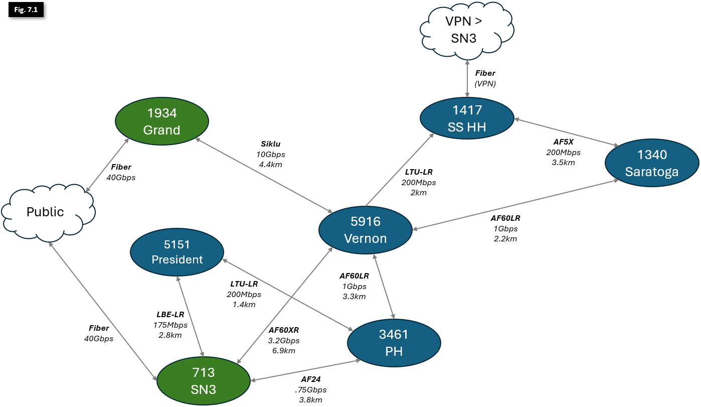 Note: some additional links and hubs omitted for clarity; listed link speeds are production single-direction actuals; distances between Hubs are not to scale
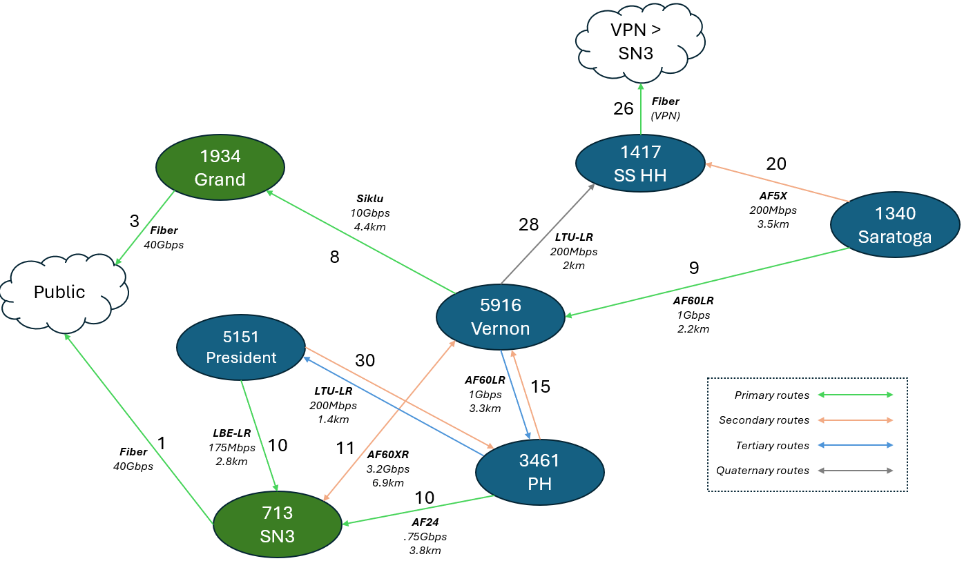
Figure 7.1 illustrates links between larger Hubs in Brooklyn, with notations indicating deployed hardware, directional link capacity and physical distance. Supernodes in green serve as Internet Exits; all other Hubs are marked in blue. As mentioned earlier in this article, all OSPF link costs are symmetrical to ensure consistent bi-directional traffic flow and ease of configuration.
Because OSPF will always prefer the lowest-cost route to an exit, its easier to work from the outside-in (i.e., starting with the Supernodes adjacent to the Internet Exits and working our way deeper into the network). To begin planning our link costs, let's start by identifying the Public Internet exits:
- Both 713 - Supernode 3, and 1934 Grand St. have 40Gbps fiber uplinks to the Public Internet. While they carry more traffic than indicated in this diagram, there is enough capacity in each of these links to comfortably carry all NYC Mesh traffic through a single Supernode if necessary. SN3 has cost 1 to exit, and Grand has cost 3.
- 1417 - Hex House (Soft Surplus) serves a number of nodes and small Microhubs, and leverages a Wireguard VPN connection over consumer fiber internet to connect to SN3. It also serves as a backup route for Vernon and Saratoga. To ensure it doesn't take too much traffic in normal network conditions, it has a total cost of 26+1=27 to exit through SN3.
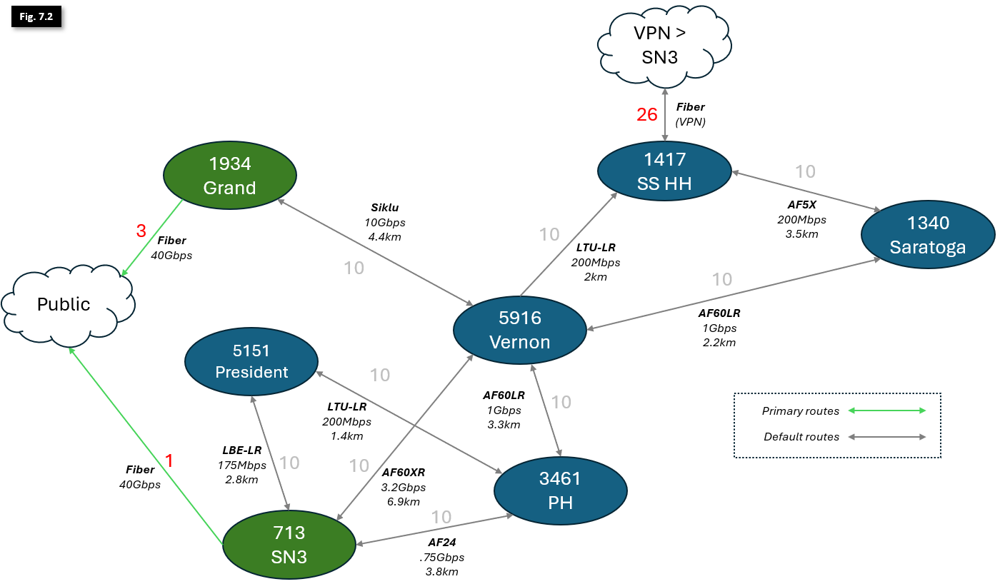
With the Public Internet exits and costs identified in red in Figure 7.2, the network will operate mostly ok with default costs of 10 (noted in grey) for all other links... until we experience outages, whether from heavy rain or rare hardware failure.
To optimize the network, we'll need to make some changes to some of our primary link costs.
- Currently, all traffic will exit through SN3. We want to change Vernon, which supports hundreds of members and dozens of Hubs, to prioritize the SIklu link over the AF60XR, increasing rain resiliency and capacity. To accomplish this, we'll need to make 2 changes:
- Decrease the Siklu link to cost 8, for a total exit cost of 8+3=11 via Grand.
- Increase the AF60XR link cost to 11, for a total backup exit cost of 11+1=12 via SN3.
- We can leave the Prospect Heights and President links as-is; these single-hop links have more than enough bandwidth to serve their local and upstream members. Both have a total exit cost of 10+1=11.
With these changes in place, Vernon now prioritizes traffic correctly over its highest-capacity link, and has a dedicated high-capacity secondary failover link in case of hardware failure or a Grand outage. Additionally, Saratoga will now also follow Vernon's exit to Grand.

We now have traffic moving more efficiently, and can operate with plenty of overhead for traffic spikes and growth. However, if we experience heavy rainfall or suffer outages, we may still have problems. We'd also like to make sure we don't have to redesign the entire OSPF schema from the ground up very time a new Hub is stood up. We'll work to address that now:
- To prefer higher-capacity links in our secondary routes, let's change the following:
- The Saratoga AF5X link cost to Soft Surplus can be increased to 20, and the PH AF60LR link to Vernon can be increased to 15 to leave some room for growth.
- To ensure PH prefers Vernon as its secondary exit, the President <> PH link can be increased to 30 and will continue to be the secondary exit for President.
- Because Saratoga and Vernon have many Microhubs between them that risk bridging these two larger Hubs (as illustrated in Figure 4), we'll decrease that link cost to 9 to mitigate this risk.
- Since we increased the Saratoga <> Soft Surplus secondary link cost, we'll also want to increase the cost of the Vernon LTU-LR link to Soft Surplus so that Saratoga and Vernon will balance their traffic across their dedicated lower-capacity Soft Surplus links if Vernon gets isolated from both Supernodes.
- Additionally, Soft Surplus and its small number of connected nodes and Microhubs should use its weather-proof fiber VPN link as their primary exit instead of traversing less resilient wireless links.
- To address both needs, we'll increase the Vernon <> Soft Surplus LTU-LR link cost to 28.
Let's see how our network looks in Figure 7.4 now that we've put these changes in place.

We now have efficient routing in place with high-resiliency backups for rain as well as high-capacity backups for hardware failures and outages!
If you've made it this far, you should have a good understanding of how to safely manage routes and costs on the Mesh, and be able to plan for new nodes and Hubs armed with a better understanding of traffic flow across the network.
To learn how to configure OSPF routes on our Mikrotik routers, see the OSPF Configuration Guide to get started.
Appendix: Brooklyn Hub OSPF Costs
Note: the routing details in this document are accurate as of April 11th, 2024. Before making production routing changes, check the NYC Mesh Node Explorer tool and discuss in our Slack #architecture channel.
1340 - Saratoga
- This hub serves a large amount of nodes and Microhubs, carrying 1-400Mbps traffic at any given moment.
- Its primary exit is through a 1.95Gbps AF60LR to Vernon, with total exit cost of 9+8+3=20 via Grand.
- This 2.2km 60GHz link occasionally experiences interruptions in heavy rain and snow.
- Its secondary exit is a 200Mbps AF5X to Hex House, with a total exit cost of 20+26+1=47.
- Although this 3.5km 5GHz link does not have enough capacity to consistently carry all local traffic, it is extremely resilient to weather impacts, making it preferrable over a high-frequency, high-capacity antenna.
3461 - Prospect Heights:
- Similar to Saratoga, this hub serves a large amount of nodes, Microhubs and Hubs, carrying 2-500Mbps traffic at any given moment
- Its primary exit is through a 750Mbps AF24 to SN3, with total exit cost of 10+1=11 via SN3.
- While this 3.8km 24GHz link has lower capacity than a similar 60GHz model, it has much better weather resiliency and experiences only a few minutes of downtime per year
- Its secondary exit is a 1.95Gbps AF60LR to Vernon, with total exit cost of 15+8+3=26 via Grand.
- This 3.3km 60GHz link is less resilient to weather, and is intended only as a failover in case the AF24 link goes down due to hardware malfunction or SN3 outage.
- Its tertiary exit is a 200Mbps LTU-LR to President - 5151, with total exit cost of 30+10+1=41 via SN3.
- Similar to Saratoga's secondary route, this 1.4km 5GHz link is extremely resilient to weather impacts.
5151- President
- While this hub serves 15-20 members, normally only carrying ~25-100Mbps in traffic, its location and height make it worthwhile to include in our analysis as it serves as a backup to multiple Hubs.
- Its primary exit is through a 175Mbps Litebeam LR to SN3, with total exit cost of 10+1=11.
- This 2.8km 5GHz link is extremely resilient to weather impacts, and given the smaller footprint and bandwidth requirements of this Hub, is preferred over 60GHz hardware.
- Its secondary exit is a 200Mbps LTU-LR to Prospect Heights, with total exit cost of 30+10+1=41 via SN3.
- It also has a tertiary 5GHz 100Mbps exit through 1635 - Park Slope (not shown in this diagram), and is secondary exit for that Hub.
5916 - Vernon
- The Vernon Hub is our largest and most heavily trafficked in Brooklyn, serving a very large number of nodes, dozens of Microhubs, and many Hubs as a primary exit to the Public Internet. Its location and height advantage over nearby neighborhoods make it a critical backbone of the Mesh. It typically carries 600-1200Mbps of traffic.
- Its primary exit is through a 10Gbps SIklu EtherHaul to Grand, with total exit cost of 8+3=11.
- This 4.4km licensed 70GHz link is fairly resilient to rain and snow, but does occasionally experience service degradation and interruptions in heavy precipitation.
- Its secondary exit is through a 3.2Gbps AF60XR link to SN3, with total exit cost of 11+1=12.
- Similar to Prospect Heights' secondary, this 6.9km 60GHz link, the longest in NYC Mesh production use, has poor weather resilience, and is intended only as a failover in case the Siklu link goes down due to hardware malfunction or Grand outage.
- Its tertiary exit is the 1.95Gbps AF60LR to Prospect Heights, with total exit cost of 15+10+1=26 via SN3.
- Similar to the secondary exit, this 60GHz 3.3km link is only intended as a bidirectional failover in case of multiple hardware failures and/or Supernode outages.
- Its quaternary exit is a 200Mbps LTU-LR to Hex House, with total exit cost of 28+26+1=55 via SN3.
- Although this 2km 5GHz link does not have enough capacity to consistently carry all local traffic, similar to Saratoga's secondary link, it is extremely resilient to weather impacts and provides an exit in cases of especially severe weather interrupting all other higher-capacity links.
Rules and Standards
As OSPF has some challenges in deployment outside of a datacenter environment, we will need to all adhere to some rules to prevent from encountering a routing problem. OSPF, unlike BGP or other protocols, may/will refuse to connect to a peer which has different parameters set and can be a source of confusion. Please follow these rules unless there is a good reason not to:
- General
- All OSPF usage will be on area
0.0.0.0( backbone area ) - Set Router ID to the 10-69-net address of the Node
- All OSPF timers will be set to ( this is typically default ):
- Link Cost 10
- Retransmit Interval 5
- Transmit Delay 1
- Hello Interval 10
- Dead Router Interval 40
- All OSPF usage will be on area
- Interfaces should be in PtMP mode (not broadcast)
- OSPF "networks" should only be the 10-69-net, unless there is a special case
- Redistribute Default Route should be
never, unless you are distributing a default route- If you are redistributing a default route, do so
as type 1 - Check with the rest of the network what the correct metric should be
- If you are redistributing a default route, do so
- Redistribute user networks via Redistribute Connected
as type 1 - Mikrotik Only: Filter VPN point-to-point /32 links. They cause trouble.
- For RouterOS 6, do not also run BGP on the standard mesh bridge, unless there is a special case; this has been known to cause problems in the past
- For RouterOS 7, BGP is working on the mesh bridge in a few locations as of July 2024; as ROS7 is not widely utilized within NYC Mesh yet, thorough testing and monitoring should be done for ROS7 routers
OSPF Configuration Guide
This guide contains in-depth parameters on Layer 2 and 3 configurations. This guide is not meant to be a comprehensive guide on overall networking, but an extension of existing concepts to solve Mesh-specific problems.
It is encouraged that you familiarize yourself with the NYC Mesh OSPF Routing Methodology to better understand the concepts and techniques in this page prior to putting these methods into practice.
What is the "Mesh bridge"?
On the Mesh, almost all routers have a "mesh bridge", which is an isolated, virtualized switch that connects home/apartment routers and radios together. All of the wireless radios on the NYC Mesh network are configured to operate in "bridge" mode, which means that the routers themselves are responsible for sending and routing packets to their neighbors which will be visible through the connected radios. As detailed in our routing methodology, this bridge is set with a standardized cost of 10 across the network to facilitate simple deployment of new equipment and ease-of-use for the volunteers that support and maintain it.
To see what OSPF interfaces are configured on a Mikrotik router on ROS6, use the routing ospf interface print command.
[admin@nycmesh-8300-omni] > routing ospf interface print
Flags: X - disabled, I - inactive, D - dynamic, P - passive
# INTERFACE COST PRIORITY NETWORK-TYPE AUTHENTICATION AUTHENTICATION-KEY
0 mesh 10 1 ptmp none
1 wds 100 1 ptmp none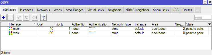
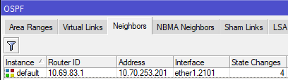
Adjacent routers in an OSPF area see each other as "neighbors", and each router is aware of all other routers in its area. On Mikrotik routers, you can see the OSPF neighbors by using the routing ospf neighbor print command.
[admin@nycmesh-8300-omni] > routing ospf neighbor print
0 instance=default router-id=10.69.83.1 address=10.69.83.1 interface=mesh
priority=1 dr-address=0.0.0.0 backup-dr-address=0.0.0.0 state="Full"
state-changes=4 ls-retransmits=0 ls-requests=0 db-summaries=0
adjacency=4h39m31s
1 instance=default router-id=10.69.5.44 address=10.69.5.44 interface=mesh
priority=1 dr-address=0.0.0.0 backup-dr-address=0.0.0.0 state="Full"
state-changes=5 ls-retransmits=0 ls-requests=0 db-summaries=0
adjacency=4h39m38s
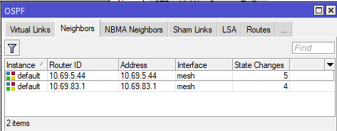
In the above example, we see that this router has two neighbors, 10.69.5.44 and 10.69.83.1, and both are on the "mesh" interface which has a cost of 10.
Why would you need a non-standard OSPF interface?
Sometimes the need will arise that a particular link should have a different cost than the mesh bridge standard, such as:
- Links between hubs to dictate preferred routes based on wireless link speed, quality, and rain resiliency
- Forcing a preferred route at a node over a backup route
- Ensuring new nodes and hubs with multiple links do not inadvertently become primary exit routes for higher-capacity hubs
- Utilizing BFD for faster failover on links with poor rain performance
The solution to this is to create a new dedicated OSPF interface (which is not on the mesh bridge) between two routers with a point-to-point address space, and a non-standard cost.
Considerations for Configuration
The implementation of an OSPF interface depends on two factors:
- If the link is Point-to-Point (two radios that only connect to each other, or a wired link), or Point-to-Multipoint (one radio connected to an access point that serves one or more other radios)
- Whether there is a switch between the router and the radio, and if it is managed or unmanaged
The following table shows the most common link types and their requirements for OSPF configuration. Note that each end of a link may have different characteristics, and therefore different requirements. Some routers and radios support VLAN tagging on egress; for the purposes of simplicity and conformity to NYC Mesh standards, VLAN interfaces should be used as follows
| Link Type | Connection to Router | VLAN Interface Required | Switch port egress |
| PtP | Direct | No | N/A |
| PtP | Through managed switch | Yes* | Untagged |
| PtMP |
Direct or through managed switch | Yes (both ends) | Tagged |
| Any | Through unmanaged (dumb) switch | Yes (both ends) | N/A (Tagged) |
Sidebar: nuances of VLAN configurations with Mikrotik and Ubiquiti Hardware
Before describing implementation steps, it's important to understand how VLANs work on switch ports; in all PtMP links, or if either end of the link has a switch between the radio and router (extremely common at NYC Mesh hubs), you will need to create VLAN interfaces on the router and instruct the switch where to send the VLAN-tagged traffic.
The first concept to understand is Ingress vs Egress Traffic
- Ingress traffic is traffic entering a physical or virtual port on a device, which is then passed to other interfaces or bridges on the local device
- Egress traffic is traffic exiting a physical or virtual port on the local device to a another connected device
- For the purposes of routing and switching tables, an ingress port is the port that traffic enters the device through, and the egress port is the port that it exits through
The second concept is a VLAN interface on Mikrotik devices, which is a virtual interface associated with a physical port that "listens for" tagged traffic through the physical port only with the specified VLAN ID, and automatically untags that traffic before passing it onto the bridge or OSPF instance. This also works in reverse; untagged traffic on the bridge or OSPF Interface can "enter" the vlan interface and is tagged before egress out the physical port.
Multiple VLAN Interfaces on a single physical router port
The third concept is VLAN behavior on switch ports. On a managed switch, generally you must define what ports are allowed to pass traffic with specific VLAN tags in the VLAN table, but you also have the ability to add, modify, and remove tags on traffic entering and exiting the switch port, which will be key for configuration later in this guide. Mikrotik and Ubiquiti use similar terminology on their switches:
- for Mikrotik switches, bridge vlan-filtering=yes must be enabled on the bridge otherwise tagged traffic will be able to ingress/egress through any port on the bridge
- Switch ports set as Tagged for a VLAN are allowed to pass both ingress and egress tagged traffic with the specified VLAN, but do not modify the tag. These are commonly used for Trunk ports.
- Switch ports set as Untagged for a VLAN will accept the tagged ingress traffic from the switch chip and strip the specified VLAN ID on egress.
- On Ubiquiti Edgepoint S16 switches, untagged ingress traffic on the port will be automatically tagged with the VLAN ID specified
- On Mikrotik devices, untagged ingress is usually not automatically tagged; this can be accomplished with the "PVID" value on the bridge port vlan setting
- Note that you must specify at least 2 ports per VLAN, otherwise the traffic will be dropped by the switch
[admin@nycmesh-219-netpower16p] /interface bridge vlan> print
Flags: X - disabled, D - dynamic
# BRIDGE VLAN-IDS CURRENT-TAGGED CURRENT-UNTAGGED
0 ;;; lbelr to PH
bridge 1072 ether1
ether15
1 bridge 99 ether1 sfp-sfpplus1
2 ;;; Revere 7985 (lbe)
bridge 2301 ether1
ether14
3 ;;; mgmt
bridge 50 ether1
ether15
ether13
4 ;;; af60 to Vernon
bridge 1092 ether1
ether13 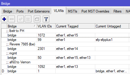
Bridge VLAN table on a Mikrotik Netpower 16P
Implementation scenarios with directly-connected antennas
The following section details the configuration steps for the scenarios listed in the table above. While this will not cover every scenario you may find, it should give you the knowledge needed to create links of varying complexity.
Important Notes: Making changes to default OSPF costs can have unintended effects, up to and including network-wide outages, and frequently requires modifying Hub configurations. Testing and learning should not be done in production environments. Before making changes to NYC Mesh routing configurations, discuss in our Slack #architecture channel and/or applicable hub channel and check the NYC Mesh Node Explorer tool for current routing information.
Before setting up secondary links, double-check that the appropriate Bridge Filters are enabled on the local router. A misconfigured or disabled Mesh Bridge Filter may result in 0-cost links between neighboring nodes and Hubs, risking major network congestion or outages.
When implementing changes in production, be mindful of order of operations and availability of backup routes; removing a remote interface from the mesh bridge will cause the link to drop and you may lose remote access to the router if there is not another OSPF neighbor visible to the router
At a high level, this configuration is simpler than it sounds.
- Reserve a point-to-point address space (/31 for Mikrotik, /30 for Juniper) for the two routers to connect
- If the data will traverse through a switch or an Access Point/PtMP antenna on either end, create VLAN interfaces on both routers for tagged traffic to traverse the link
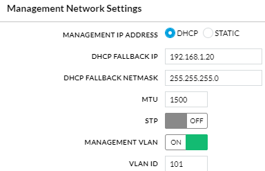
- On the non-AP side, create a second VLAN interface for management access to the radio, added to the mesh bridge, and set the radio's management VLAN to match
- Add the IP addresses from the point-to-point address space to the interfaces on both ends
- Add the physical (for PtP with no switches) or VLAN interfaces as OSPF interfaces on the routers as "PTMP" network type with bfd enabled
- Add the point-to-point OSPF address space to the backbone
- On the non-AP side(s), remove/disable the physical interface from the Mesh bridge so data can only traverse through the new OSPF interface
- If data will traverse through a switch, update the switch vlan table to allow tagged traffic to pass
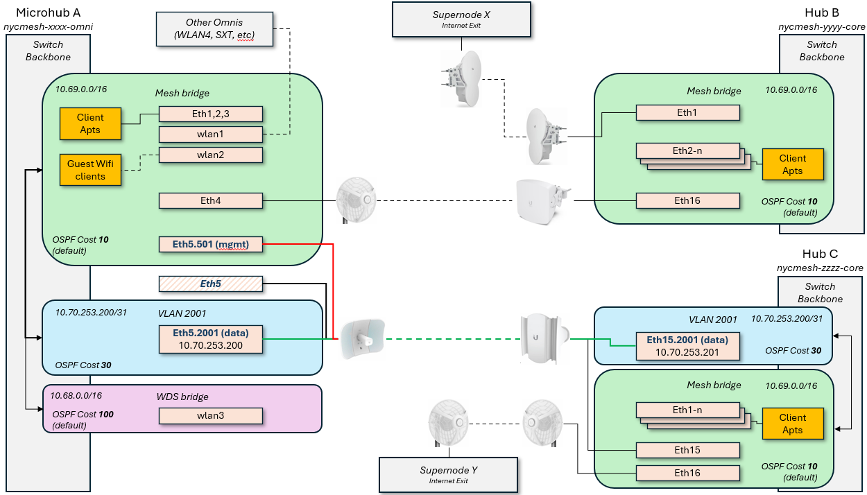
This diagram shows how this would look logically for a Microhub on the left to connect to two different Hubs with separate exits; this grants automatic failover for Microhub A in the event that the primary link, or Hub B / Supernode X goes down.
Scenario 1: Point to Point with directly-attached antennas
Router A > untagged > Antenna A <> Antenna B < untagged < Router B
This is the simplest configuration, as each end of the link has an antenna (or hardwire) plugged directly into the routers on each end. Because all traffic through the link should be on the new interface, we do not need to create any VLAN interfaces; the physical port itself can be removed from the Mesh bridge and added as a standalone OSPF interface with adjusted cost.
- If performing this on a remote site, ensure the link being adjusted is not a single point of failure before proceeding
- Reserve an unused /31 IP range to be used for the OSPF network (ask in the #architecture channel for access to the IP ranges sheet for more information on this)
- For this example, I will use 10.70.253.200/31
- If one or both of the routers is running Juniper OS, you will need a /30 reservation
- On each router, add the reserved IPs and network to the appropriate interfaces
RouterA: /ip address add address=10.70.253.200 network=10.70.253.201 interface=ether1 RouterB: /ip address add address=10.70.253.201 network=10.70.253.200 interface=ether5You can verify they were added correctly with /ip address print
[admin@nycmesh-8300-omni] > ip address print Flags: X - disabled, I - invalid, D - dynamic # ADDRESS NETWORK INTERFACE 0 10.104.27.1/26 10.104.27.0 mesh 1 10.69.83.0/16 10.69.0.0 mesh 2 10.68.83.0/16 10.68.0.0 wds 3 10.70.253.200/32 10.70.253.201 ether1 - On each router, add the physical port as an OSPF interface with the correct cost, set for "PTMP", and enable BFD. For this example, I will use cost 9.
You can verify they were added correctly with /routing ospf interface printRouterA: /routing ospf interface add cost=9 interface=ether1 network-type=ptmp use-bfd=yes RouterB: /routing ospf interface add cost=9 interface=ether5 network-type=ptmp use-bfd=yes
[admin@nycmesh-8300-omni] > routing ospf interface print Flags: X - disabled, I - inactive, D - dynamic, P - passive # INTERFACE COST PRIORITY NETWORK-TYPE AUTHENTICATION AUTHENTICATION-KEY 0 mesh 10 1 ptmp none 1 wds 100 1 ptmp none 2 ether1 9 1 ptmp none - On each router, add the OSPF Network so the OSPF interface is routable. Note that this command is identical on both ends.
You can verify they were added correctly with /routing ospf network printRouterA: /routing ospf network add area=backbone network=10.70.253.200/31 RouterB: /routing ospf network add area=backbone network=10.70.253.200/31
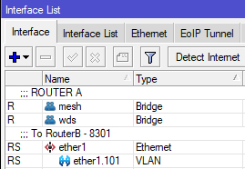
[admin@nycmesh-8300-omni] > routing ospf network print Flags: X - disabled, I - invalid # NETWORK AREA 0 10.69.0.0/16 backbone 1 10.68.0.0/16 backbone 2 10.70.253.200/31 backbone - On each router, remove the PtP interface from the Mesh Bridge. This should be done on the remote router first, as you will lose connectivity to the remote device until the local device is updated and the neighbors are re-established
You can verify this is set correctly with /interface bridge port print. For 0 - ether1, the "X" indicates the port is disabledRouter B: /interface bridge port set 4 disabled=yes Router A: /interface bridge port set 0 disabled=yes
[admin@nycmesh-8300-omni] > interface bridge port print; Flags: X - disabled, I - inactive, D - dynamic, H - hw-offload # INTERFACE BRIDGE HW PVID PR PATH-COST INTERNA... HORIZON 0 XI ether1 mesh 1 0x 10 10 none 1 I ether2 mesh no 1 0x 10 10 none 2 I ether3 mesh no 1 0x 10 10 none 3 I ether4 mesh no 1 0x 10 10 none 4 I ether5 mesh no 1 0x 10 10 none 5 I wlan1 mesh 1 0x 10 10 none 6 I wlan2 mesh 1 0x 10 10 none 7 I wlan4 mesh 1 0x 10 10 none 8 I wlan3 wds 1 0x 10 10 none 9 dynamic wds yes 1 0x 100 100 none - Once the bridge ports are disabled on both ends, the OSPF link will activate and establish adjacency; you can validate this on either router with /routing ospf neighbor print
[admin@nycmesh-8300-omni] > /routing ospf neighbor print 0 instance=default router-id=10.69.83.1 address=10.70.253.201 interface=ether1 priority=1 dr-address=0.0.0.0 backup-dr-address=0.0.0.0 state="Full" state-changes=9 ls-retransmits=0 ls-requests=0 db-summaries=0 adjacency=6m30s
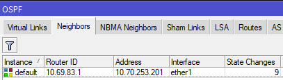
Now we have established a 9-cost OSPF link between the two routers! This cost can be changed at will as the network topology changes in the future.
Scenario 2: Point to Multipoint with directly attached antennas
Router A > tagged > Antenna A <> Access Point B < tagged < Router B
This set up is more complicated, because we need to be able to establish a new OSPF session between Router A and RouterB without impacting its existing mesh interface neighbors that are also connected to Access Point B. Unlike the previous example, we need a way for RouterB to know to only send RouterA's traffic to the new OSPF interface, but leave all the other traffic on the default mesh interface.
This is where VLAN interfaces come into play - tagging the traffic with a VLAN ID will allow the traffic to be routed correctly. In this case, we will only be removing the physical port from the mesh bridge on Router A, detailed below
- Reserve an unused /31 IP range and VLAN ID to be used for the OSPF network (ask in the #architecture channel for access to the IP ranges sheet for more information on this)
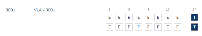
- For this example, I will again use 10.70.253.200/31, and VLAN ID 3001
- For this example, I will again use 10.70.253.200/31, and VLAN ID 3001
- To ensure we don't lose access to Antenna A's management portal later, create a VLAN interface on RouterA for management and add it to the mesh bridge; this can be any VLAN ID, as long as the same ID isn't being used for management on the other end of the link (because we don't want the two routers to see each other on this vlan). We normally use a X01 VLAN ID related to the physical port. In our case, because the antenna is on ether1, I will use 101.
RouterA: /interface vlan add interface=ether1 name=ether1.101 vlan-id=101 RouterA: /interface bridge port add bridge=mesh interface=ether1.101
- On the antenna, set the Management VLAN ID to match the VLAN you just added and save; you should retain connectivity.

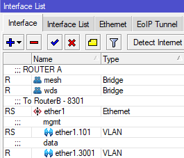
- On each router, create a vlan interface for VLAN 3001 on the physical port the antennas are connected to. We need to use the same VLAN on both ends whenever we traverse through an Access Point to keep this traffic identifiable on both ends of the link. Note that you will not add these interfaces to the mesh bridge.
RouterA: /interface vlan add interface=ether1 name=ether1.3001 vlan-id=3001 RouterB: /interface vlan add interface=ether5 name=ether1.3001 vlan-id=3001
- On each router, add the reserved IPs and network to the appropriate VLAN 3001 interfaces
RouterA: /ip address add address=10.70.253.200 network=10.70.253.201 interface=ether1.3001 RouterB: /ip address add address=10.70.253.201 network=10.70.253.200 interface=ether5.3001You can verify they were added correctly with /ip address print
On each router, add the vlan interface as an OSPF interface with the correct cost, set for "PTMP", and enable BFD. For this example, I will again use cost 9.[admin@nycmesh-8300-omni] > ip address print Flags: X - disabled, I - invalid, D - dynamic # ADDRESS NETWORK INTERFACE 0 10.104.27.1/26 10.104.27.0 mesh 1 10.69.83.0/16 10.69.0.0 mesh 2 10.68.83.0/16 10.68.0.0 wds 3 10.70.253.200/32 10.70.253.201 ether1.3001
You can verify they were added correctly with /routing ospf interface printRouterA: /routing ospf interface add cost=9 interface=ether1.3001 network-type=ptmp use-bfd=yes RouterB: /routing ospf interface add cost=9 interface=ether5.3001 network-type=ptmp use-bfd=yes
[admin@nycmesh-8300-omni] > routing ospf interface print Flags: X - disabled, I - inactive, D - dynamic, P - passive # INTERFACE COST PRIORITY NETWORK-TYPE AUTHENTICATION AUTHENTICATION-KEY 0 mesh 10 1 ptmp none 1 wds 100 1 ptmp none 2 ether1.3001 9 1 ptmp none - On each router, add the OSPF Network so the OSPF interface is routable.
You can verify they were added correctly with /routing ospf network printRouterA: /routing ospf network add area=backbone network=10.70.253.200/31 RouterB: /routing ospf network add area=backbone network=10.70.253.200/31
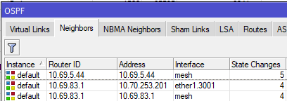
[admin@nycmesh-8300-omni] > routing ospf network print Flags: X - disabled, I - invalid # NETWORK AREA 0 10.69.0.0/16 backbone 1 10.68.0.0/16 backbone 2 10.70.253.200/31 backbone - At this point, the two routers should establish adjacency on the VLAN interfaces, and if the cost is <10, then traffic will prefer that route.
[admin@nycmesh-8300-omni] > /routing ospf neighbor print 0 instance=default router-id=10.69.83.1 address=10.70.253.201 interface=ether1.3001 priority=1 dr-address=0.0.0.0 backup-dr-address=0.0.0.0 state="Full" state-changes=4 ls-retransmits=0 ls-requests=0 db-summaries=0 adjacency=47s 1 instance=default router-id=10.69.83.1 address=10.69.83.1 interface=mesh priority=1 dr-address=0.0.0.0 backup-dr-address=0.0.0.0 state="Full" state-changes=4 ls-retransmits=0 ls-requests=0 db-summaries=0 adjacency=11m26s
- The last step is to remove RouterA's physical port from the mesh bridge, so that traffic can only route through the new VLAN interface you have created. Note that we do not do this step on RouterB, because we want the untagged traffic from other connected antennas to continue to enter the mesh bridge.
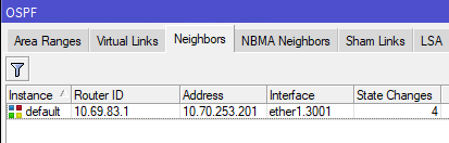
Now, OSPF Neighbors will only show the VLAN interface and you are done!Router A: /interface bridge port set 0 disabled=yes

Implementation scenarios where a switch exists between the antennas and routers
Scenario 3: Point to Multipoint with a switch at one or both ends
Router A > tagged > Antenna A <> Access Point B < tagged < Switch B < tagged < Router B
This is one of the most common scenarios you'll encounter in the NYC Mesh network; many multi-member nodes and smaller hubs have a high-capacity 60Ghz radio with a backup 5Ghz radio to the same or a different hub for failover in heavy rain. This scenario is almost identical to Scenario 2, with one important caveat: we have to configure the switch to pass the VLAN traffic to the appropriate switch port.
- Reserve an unused /31 IP range and VLAN ID to be used for the OSPF network (ask in the #architecture channel for access to the IP ranges sheet for more information on this)
- For this example, I will again use 10.70.253.200/31, and VLAN ID 3001
- For this example, I will again use 10.70.253.200/31, and VLAN ID 3001
- To ensure we don't lose access to Antenna A's management portal later, create a VLAN interface on RouterA for management and add it to the mesh bridge; this can be any VLAN ID, as long as the same ID isn't being used for management on the other end of the link. We normally use a X01 VLAN ID related to the physical port. In our case, because the antenna is on ether1, I will use 101.
RouterA: /interface vlan add interface=ether1 name=ether1.101 vlan-id=101 RouterA: /interface bridge port add bridge=mesh interface=ether1.101 - On Antenna A, set the Management VLAN ID to match the VLAN you just added and save; you should retain connectivity.
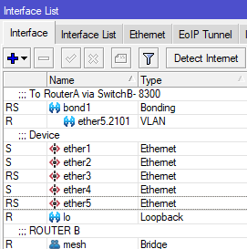
- On each router, create a vlan interface for VLAN 3001 on the physical port the antenna/switch is connected to. For this example, let's assume that RouterB uses the bond1 interface to connect to the Switch.
RouterA: /interface vlan add interface=ether1 name=ether1.3001 vlan-id=3001 RouterB: /interface vlan add interface=bond1 name=bond1.3001 vlan-id=3001
Note: If there is a bonded/LAG interface (where multiple SFP/ethernet ports are used for uplink), then you should put the vlan interface on the bonded interface - On each router, add the reserved IPs and network to the appropriate VLAN 3001 interfaces
RouterA: /ip address add address=10.70.253.200 network=10.70.253.201 interface=ether1.3001 RouterB: /ip address add address=10.70.253.201 network=10.70.253.200 interface=bond1.3001 - On each router, add the vlan interface as an OSPF interface with the correct cost, set for "PTMP", and enable BFD. For this example, I will again use cost 9.
RouterA: /routing ospf interface add cost=9 interface=ether1.3001 network-type=ptmp use-bfd=yes RouterB: /routing ospf interface add cost=9 interface=bond1.3001 network-type=ptmp use-bfd=yes - On each router, add the OSPF Network so the OSPF interface is routable.
RouterA: /routing ospf network add area=backbone network=10.70.253.200/31 RouterB: /routing ospf network add area=backbone network=10.70.253.200/31 - Here is where we diverge from Scenario 2: we must configure Switch B to pass the tagged traffic to the correct egress port. In this example, let's assume the trunk port to the router is also bond1, and the Access Point is on ether8 on a Mikrotik switch
If not already enabled, we also need to enable vlan-filtering on the SwitchB bridge and ether8.SwitchB: /interface bridge vlan add bridge=bridge tagged=ether8,bond1 vlan-ids=3001
If the switch is a Ubiquiti S16, you would add the VLAN ID and set the trunk and AP ports as Tagged for VLAN 3001, and exclude all other portsSwitchB: /interface bridge set 0 vlan-filtering=yes ether-type=0x8100 pvid=1 frame-types=admit-all SwitchB: /interface bridge port set 7 vlan-filtering=yes ingress-filtering=yes

Note: If there is also a switch between Router A and Antenna A, repeat step 8 on Switch A to allow tagged traffic to pass to the appropriate port
- The two routers should establish adjacency on the VLAN interfaces, and if the cost is <10, then traffic will prefer that route.
[admin@nycmesh-8300-omni] > /routing ospf neighbor print 0 instance=default router-id=10.69.83.1 address=10.70.253.201 interface=ether1.3001 priority=1 dr-address=0.0.0.0 backup-dr-address=0.0.0.0 state="Full" state-changes=4 ls-retransmits=0 ls-requests=0 db-summaries=0 adjacency=47s 1 instance=default router-id=10.69.83.1 address=10.69.83.1 interface=mesh priority=1 dr-address=0.0.0.0 backup-dr-address=0.0.0.0 state="Full" state-changes=4 ls-retransmits=0 ls-requests=0 db-summaries=0 adjacency=11m26s - The last step is to remove RouterA's physical port from the mesh bridge, so that traffic can only route through the new VLAN interface you have created. Note that we do not do this step on RouterB, because we want the untagged traffic from other connected antennas to continue to enter the mesh bridge.
Router A: /interface bridge port set 0 disabled=yes - Now, OSPF Neighbors will only show the VLAN interface and you are done!
Scenario 4: Point to Point with switches on one end
Router A > untagged > Antenna A <> Antenna B < untagged < Switch B < tagged < Router B
This is another common scenarios you'll encounter in the NYC Mesh network, where two hubs connect to each other with dedicated antennas. Similar to Scenario 2, we have to configure the switch to pass the VLAN traffic to the appropriate switch port; but on router A, we do not need a VLAN since the antenna is plugged directly into Router A.
- Reserve an unused /31 IP range to be used for the OSPF network (ask in the #architecture channel for access to the IP ranges sheet for more information on this)
- For this example, I will again use 10.70.253.200/31
- For this example, I will again use 10.70.253.200/31
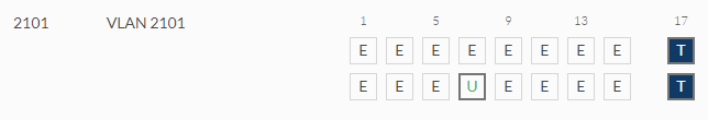
- Create a vlan interface with a VLAN of your choice on the physical port the switch is connected to; if there are switches on both ends of the link, do the same on the other end (the VLANs do not have to be the same, but can be if you choose). For this example, let's assume that RouterB uses the bond1 interface to connect to the Switch, and we will use VLAN 2101.
RouterB: /interface vlan add interface=bond1 name=bond1.2101 vlan-id=2101
Note: If there is a bonded/LAG interface (where multiple SFP/ethernet ports are used for uplink), then you should put the vlan interface on the bonded interface - On each router, add the reserved IPs and network to the appropriate physical or virtual interfaces. Because RouterA connects directly to AntennaA, we add the address to ether1; for RouterB, we use the bond1.2101 interface we just created in step 2.
RouterA: /ip address add address=10.70.253.200 network=10.70.253.201 interface=ether1 RouterB: /ip address add address=10.70.253.201 network=10.70.253.200 interface=bond1.2101 - On each router, add the applicable interface as an OSPF interface with the correct cost, set for "PTMP", and enable BFD. For this example, I will again use cost 9.
RouterA: /routing ospf interface add cost=9 interface=ether1 network-type=ptmp use-bfd=yes RouterB: /routing ospf interface add cost=9 interface=bond1.2101 network-type=ptmp use-bfd=yes - On each router, add the OSPF Network so the OSPF interface is routable.
RouterA: /routing ospf network add area=backbone network=10.70.253.200/31 RouterB: /routing ospf network add area=backbone network=10.70.253.200/31 - Here is where we diverge from Scenario 1 & 3: we must configure Switch B to pass the tagged traffic to the correct egress port and untag it on egress. We again assume the trunk port to the router is also bond1, and AntennaB is on ether8 on a Mikrotik switch. We need to set the trunk port to RouterB as tagged, and the access port to AntennaB as untagged
SwitchB: /interface bridge vlan add bridge=bridge tagged=bond1 untagged=ether8 vlan-ids=2101Additionally, we need to instruct the Mikrotik switch to tag ingress traffic with the appropriate VLAN ID. If not already set, enable vlan-filtering on the switch bridge. Then, on ether8 set the PVID to 2101, enable ingress filtering, and set the port to only allow untagged traffic on ingress (optional, but recommended for security purposes).
If the switch is a Ubiquiti S16, you only need to set the tagged and untagged port, and exclude ether8 from whatever it is currently set as untagged for:SwitchB: /interface bridge set 0 vlan-filtering=yes ether-type=0x8100 pvid=1 frame-types=admit-all SwitchB: /interface bridge port set 7 vlan-filtering=yes pvid=2101 frame-types=admit-only-untagged-and-priority-tagged ingress-filtering=yes

- The last step is to remove RouterA's physical port from the mesh bridge, so that traffic can only route through the new OSPF interface you have created. Note that we do not do this step on RouterB, because we want the untagged traffic from other connected antennas to continue to enter the mesh bridge.
If, however, RouterA also had a switch in between, then you would not remove the interface from the bridge port and instead repeat step 6 on SwitchA.Router A: /interface bridge port set 0 disabled=yes - Now, OSPF Neighbors will only show the VLAN interface and you are done!

Juniper Point-to-Point Guide
Note: This guide is even further in-depth than the Point-to-Point configuration guide. This is only intended for a technical audience who is looking to create an NYCMesh P2P, when one or both sides of the link is routed by a Juniper router.
Overview
To create a mesh-specific OSPF P2P link on the Juniper, there are 4 configuration changes you will need to make
- Create an irb interface - creating an irb interface is the Juniper equivalent of creating a MikroTik VLAN interface, or a Brocade virtual interface (ve). It's an interface with an IP address, that is assigned to a certain VLAN. The only difference is that this VLAN is not limited to a port, and can be sent out any port. This is where you will assign your /30 P2P IP address.
- Create a VLAN - the VLAN and the irb interface are be linked together, and the VLAN is assigned to the switch port that the P2P traffic will come from. This will either be a switchport that the antenna is directly connected to, or a switchport that goes to another switch, which is connected to the antenna.
- Configure OSPF on the irb - this is where you configure the OSPF cost of your P2P.
- Add the VLAN to a switchport - this is where you assign the VLAN to the port where P2P traffic will be coming from on the Juniper
Prerequisites
- Subnet allocated using the IP Ranges spreadsheet
- P2P already configured on the MikroTik side of the link (follow this guide)
- Note that for the Mikrotik IP address, you need to set the IP address to
<IP_ADDRESS>/30, and the Network will automatically set itself to the correct /30 base address
- Note that for the Mikrotik IP address, you need to set the IP address to
- OSPF cost known
Choosing a VLAN ID
In order to create a P2P, we need to choose an unused VLAN on the Juniper.
- Log into the Juniper with
ssh root@ip_address - Enter
cliat the initial prompt to enter the switch configuration - Enter
show vlansand press enter. This will display a list of all the VLANs on the Juniper. Note down a tag that is unused (this can be anything between 1 and 4094, but you should keep it close to other existing VLANs)
Configuring the Juniper
- At the main Juniper CLI prompt (where you should be after entering
show vlansabove), enterconfigureto start configuring the router. - First, we'll create the irb. Enter the following commands, replacing
<P2P_NAME>with the name of your P2P link, and<IP_ADDRESS>with the IP address of the Juniper side of the link.set interfaces irb unit <VLAN_TAG> description <P2P NAME>set interfaces irb unit <VLAN_TAG> family inet address <IP_ADDRESS>/30
- Next, create a VLAN and link it to your irb interface, replacing variables as needed.
set vlans <P2P_NAME> vlan-id <VLAN_TAG>set vlans <P2P_NAME> l3-interface irb.<VLAN_TAG>
- Next, configure OSPF on the interface. Note the PTMP setting, meaning the OSPF configuration is Point to Multi Point and not Point to Point, NBMA (Non-Broadcast Multiple Access), or Broadcast (more info on the different types here)
set protocols ospf area 0.0.0.0 interface irb.<VLAN_TAG> interface-type p2mpset protocols ospf area 0.0.0.0 interface irb.<VLAN_TAG> metric <OSPF_COST>
- (Optional: if the MikroTik side of the link is using Bidirectional Forwarding Detection (aka BFD, a faster way of detecting when a link is down than the built-in OSPF method), configure that here. If you don't know, disregard these steps)
set protocols ospf area 0.0.0.0 interface irb.<VLAN_TAG> bfd-liveness-detection minimum-interval 200set protocols ospf area 0.0.0.0 interface irb.<VLAN_TAG> bfd-liveness-detection multiplier 5set protocols ospf area 0.0.0.0 interface irb.<VLAN_TAG> bfd-liveness-detection full-neighbors-only
- Now add the VLAN to the switchport where the P2P is coming from (usually a switch)
- To figure out what interface goes to which switch, enter the command
run show interfaces description. This will list all of the ports and their descriptions. Note the interface name (examplexe-0/0/4) that the switch or antenna is connected to. Note: if the switch is connected to a bond (known as ae interfaces in Juniper) be sure to add the vlan to that port. - Add the vlan with
set interfaces <INTERFACE> unit 0 family ethernet-switching vlan members <P2P_NAME>
- To figure out what interface goes to which switch, enter the command
- Type
committo save your configuration. Once the commit succeeds, typeexitto leave configuration mode. - If there are upstream switches that your P2P VLAN needs to be added to, add them normally according to the guide listed in prerequisites.
- To confirm OSPF comes up on the Juniper, enter
show ospf neighbor, and the router will give you a list of neighbors, and their connected interfaces.