MeshDB Schema Design
Background
(updated September 2024 based on schema changes)
Background
MeshDB is an software application which replaces the New Node Responses Google Sheet (the spreadsheet) as the source of truth for NYCMesh member, install, geolocation, device, and connection information via a proper SQL database. It is built in the Django ORM, using Python Model objects to represent underlying database schema structures. In this document, we summarize the database schema and explain a variety of edge case that occur on the mesh, detailing how the edge case is represented under the MeshDB schema
The Schema (Simplified)
simplified)
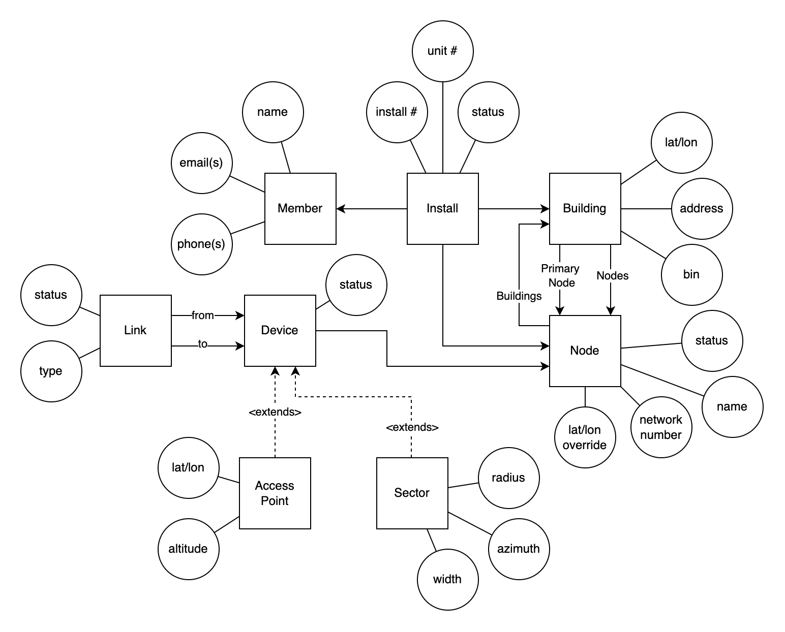
The following diagram depicts the schema, showing the relationships between models (SQL tables), and some key attributes of each model. For clarity, non-essential attributes are omitted (see appendix A for a comprehensive diagram).
We have the following models:
- Member - Represents a single NYC Mesh Member (even if they have moved between multiple addresses and therefore have multiple installs or "own" multiple active installs ). Tracks their name, email address, and other contact details
- Install - Represents the deployment (or potential deployment) of NYC Mesh connectivity to a single household. This most closely maps to the concept of a row in the spreadsheet. Tracks the unit number of the household, which member lives there, and which building the unit is located within. It also contains an install number, which corresponds to row number on the spreadsheet. With foreign keys to Member, Building, and Node, it acts as the central model, tying most of the schema together. Many objects have a status field, but the install status field maps most closely onto the status tracked in the spreadsheet.
- Building - Represents a location in NYC identified by a single street address (house number and street name). In the case of large physical structures with more than one street address, we will store one Building object for each address that we have received Install requests for. Buildings track a primary node, to represent the "colloquial network number" used by volunteers to describe the site. In the case that a building has more than one network number, the primary node will be set based on the network number that volunteers designate as the “primary” (usually the first assigned, busiest router, etc.)
- Node - Represents the abstract concept of a an NYC Mesh "site". Most closely corresponds to a dot on the map. Most concretely, this refers to a collection of NYC Mesh devices with the same network number. Each node has a single network number. A node can be assigned to multiple "building" objects, in the case that a single device powers multiple adjacent buildings or in the case that a single physical structure has more than one street address.
- Device - Represents a networking device (router, AP, P2P antenna, etc.). Contains a mandatory foreign key to node, which will be set based on the NN of the device, or of the “first hop” router used by this device (for devices like APs which have no NN assigned).
- Sector - A special type of device (using Django Model Inheritance to inherit all fields from device) which adds additional fields related to the display of sector coverage information on the map (azimuth, width, and radius)
- Access Point - A special type of device (using Django Model Inheritance to inherit all fields from device) which adds additional fields related to the display of APs on the map. It contains lat/lon override fields, which can be used to refine the exact location of this device for map display
- Link - A connection between devices, which represents a cable or wireless link, whether directly between the devices or via other antennas not represented with their own device objects
- LOS - Identifies a pair of building objects which can see each other. Renders as a "potential" link on the map display (if not superseded by an active Link object connecting the same dots). This can be populated manually by volunteers, or in the future, automatically by analysis tools
UUID Keys, Omitted Columns & Tables, and State Drift
NB: the examples used in this document reference integer primary and foreign keys. This is for simplicity of understanding only. The real system uses UUID based keys for all tables. For brevity, we also use comma separated foreign keys in place of a join table for the Node <-> Building M2M relationship. We omit tables and columns that are not directly relevant to the edge case (e.g. Member, LOS) but these are likely present in the real dataset. Additionally, these sites may have evolved since this document was written (September 2024). Please use the site descriptions below as the source of truth for the "real world" state of these locations, rather than say, climbing up on a roof and checking for yourself.
Overall, this document is conceptually accurate, but to get the full implementation details for a database migration, code change, etc. please consult the Python model definitions, and the Postgres SQL DDL directly.
Example 1 - NN492 - Typical Multi-Tenant Install

In this simple example, we have two tenants in a single building with a single address, both connected via cables directly to an omni on their shared roof. They are connected to the rest of the mesh via an LBE to Saratoga. The database tables for this scenario look like this:
Installs |
||
Install Number |
|
Building |
13134 |
|
|
13276 |
|
|
Buildings
ID
Primary NN
Address
BIN
1
492
216
3079532
| Devices |
||
| ID | ||
ID
Network Number
lat/lon overrides
1
492
-
| Links |
||
| ID | ||
ID
From Device
To Device
1
1
<saratoga sector device id>
Example 2 - NN 4734 - Cross-Building Installs

In this example, members in 3 adjacent buildings, each with their own address, are connected via a single omni, with cable runs across the roofs directly to the member’s apartments. They are connected to the rest of the mesh via an mant 802.11 sector at 4507. The database tables for this scenario look like this:
Installs |
||
Install Number |
|
Building |
4734 |
|
|
6972 |
|
|
13663 |
|
|
Buildings
ID
Primary NN
Address
BIN
2
4734
31 Clarkson Ave
3115982
3
4734
25 Clarkson Ave
3115985
4
4734
27 Clarkson Ave
3115984
| Devices |
||
| ID | ||
ID
Network Number
lat/lon overrides
2
4734
-
| Links |
||
| ID | ||
ID
From Device
To Device
2
2
<4507 sector device id>
Example 3 - 7th Street (NN 731) - Multiple Omnis on one building

In this example, we have one regular tenant in a single building with a single address. However there is also a rooftop office with its own omni, connected wirelessly to the primary one. They are connected to the rest of the mesh via a GBELR to Grand. The database tables for this scenario look like this:
Installs |
||
Install Number |
|
Building |
731 |
|
|
12985 |
|
|
Buildings
ID
Primary NN
Address
BIN
5
731
190
1086499
Devices
ID
Network Number
lat/lon overrides
3Devices
731
-
4
311
x,
Links
ID
From Device
To Device
3Links
3
4
4
3
Device
301 301 302 302 301 < 1932Example 4 - Vernon (NN 5916) - Courtyard APs
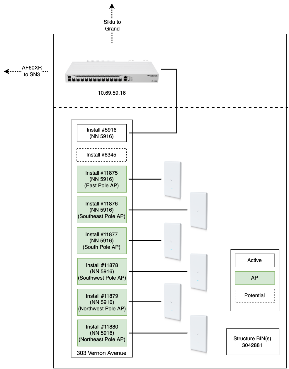
In this example, we have a core hub site in a single building with a single address. However, there are many Access Points (APs) on light poles in the building’s courtyard. These light-poles are unquestionably associated with the same building/address as the core router of this hub, but need to be shown separately on the map.
In this scenario,Here we treatuse the lightAccess polesPoint asobject ifto theyrepresent areeach “apartments”AP, inand we use the Vernonlat/lon building.on Theythese eachrows getto their own install #, but imagining a tenant living inspecify the lightlocation pole, we say that this imaginary install is “connected via” a device object representingfor the AP.map Thedots. networkAlso, numberfor legacy reasons, the installs for these APs isare setincluded to 5916, reflecting their first hop router (andfrom the factspreadsheet they(but are not themselves assigned NNs). Links betweenneeded, the courtyardAP APsdevices and the core routeralone are included so that they are rendered on the map sufficient)
The database tables for this scenario look like this:
Installs |
||
Install Number |
|
Building |
5916 |
|
|
6345 |
|
|
11875 |
|
|
11876 |
|
|
11877 |
|
|
11878 |
|
|
11879 |
|
|
11880 |
|
|
| Access
|
|||
| ID | |||
ID
PrimaryLon
NN
Address
BIN
6
5916
303 Vernon Avenue
3042881
Devices
ID
Network Number
lat/lon overrides
5Links
5916
-
6
5916
x, y
7
5916
x, y
8
5916
x, y
9
5916
x, y
10
5916
x,1934 y
11
5916
x,162 y
*there
Linksfor each of the APs in the Devices PostgresSQL table and API responses, but we hide these from the admin UI to reduce confusion
ID
From Device
To Device
5
5
<SN3 device id>
6
5
<grand device id>
7
8
9
8
8
6
9
6
5
Example 5 - Prospect Heights (NN 3461) - Multiple NNs for one building
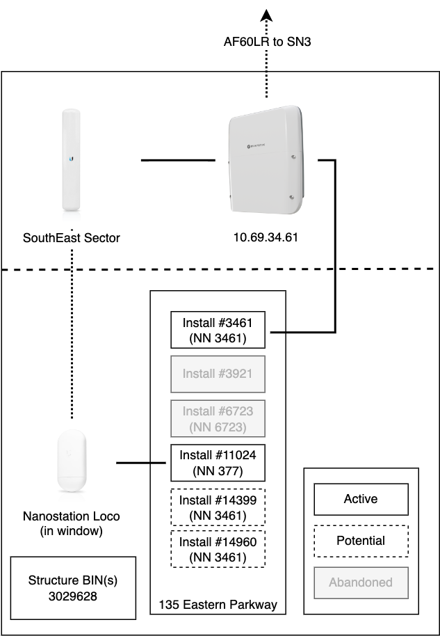
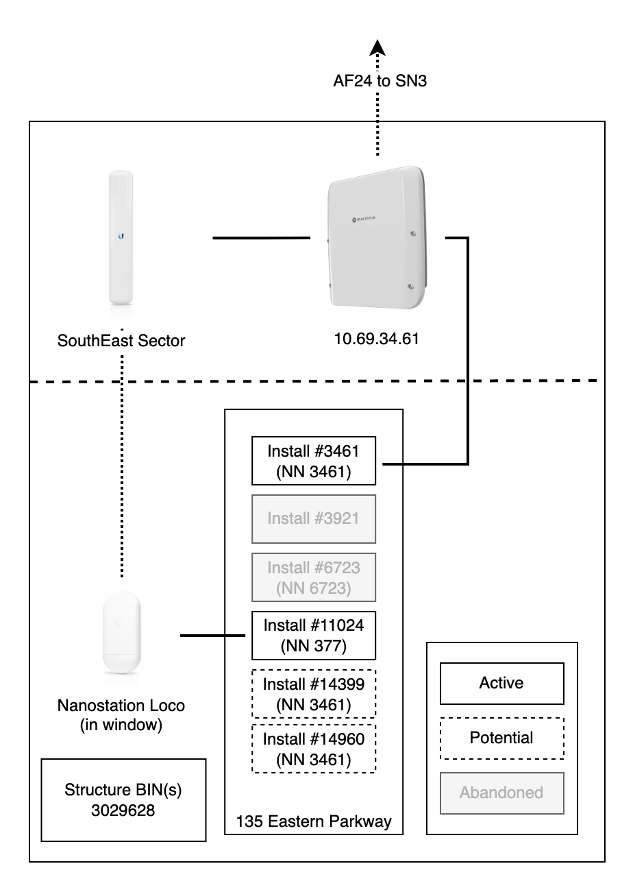
In this example, we have a core hub site in a single building with a single address. The primary NNNN, 3461, also serves a member’s apartment as install #3461. However, there is another apartment which could not due to practical considerations be connected via a cable, and had to be connected via an antenna in their window to a sector on the roof. This antenna needed an NN for configen and naming, and so this building received multiple NNs.
The database tables for this scenario look like this:
Installs |
||
Install Number |
|
Building |
3461 |
3461 |
|
3921 |
|
|
6723 |
|
|
11024 |
377 |
|
14399 |
|
|
14960 |
|
|
Buildings
ID
Primary NN
Address
BIN
7
3461
135
3029628
Devices
ID
Network Number
lat/lon overrides
12Devices
3461
-
13
377
x,
Links
ID
From Device
To Device
10Links
12
<SN3 device id>
11
13
12
Example 6 - Jefferson (NN 3606) - Multiple NNs for multiple buildings

In this example, we have a building with 4 addresses and 3 omnis on the roof, each with its own network number. There is no clean mapping between NNs and addresses, since each omni serves installs in multiple buildings. The omni of the primary NN, 3606, provides the uplink to Hex House (NN 1417). There are additional backup links, not shown here for simplicity.
The database tables for this scenario look like this:
Installs (omitting abandoned & potential for brevity) |
||
Install Number |
|
Building |
3606 |
|
|
5933 |
|
|
7177 |
|
|
8152 |
|
|
8274 |
|
|
8085 |
|
|
Buildings |
||||
ID |
Primary |
|
Address | |
BIN
8
3606
5933, 169
476 Jefferson Street3819572
9
3606
5933, 169
488 Jefferson Street3819572
10
3606
5933, 169
28 Scott Avenue3819572
11
3606
5933, 169
16 Cypress Avenue3819572
Devices
ID
Network Number
lat/lon overrides
14Links
3606
x, y
15
5933
x, y
16
169
x,1417 y
Links
ID
From Device
To Device
12
14
<1417 device id>
13
14
15
14
15
16
15
16
14
Appendix A - Full Schema Diagram
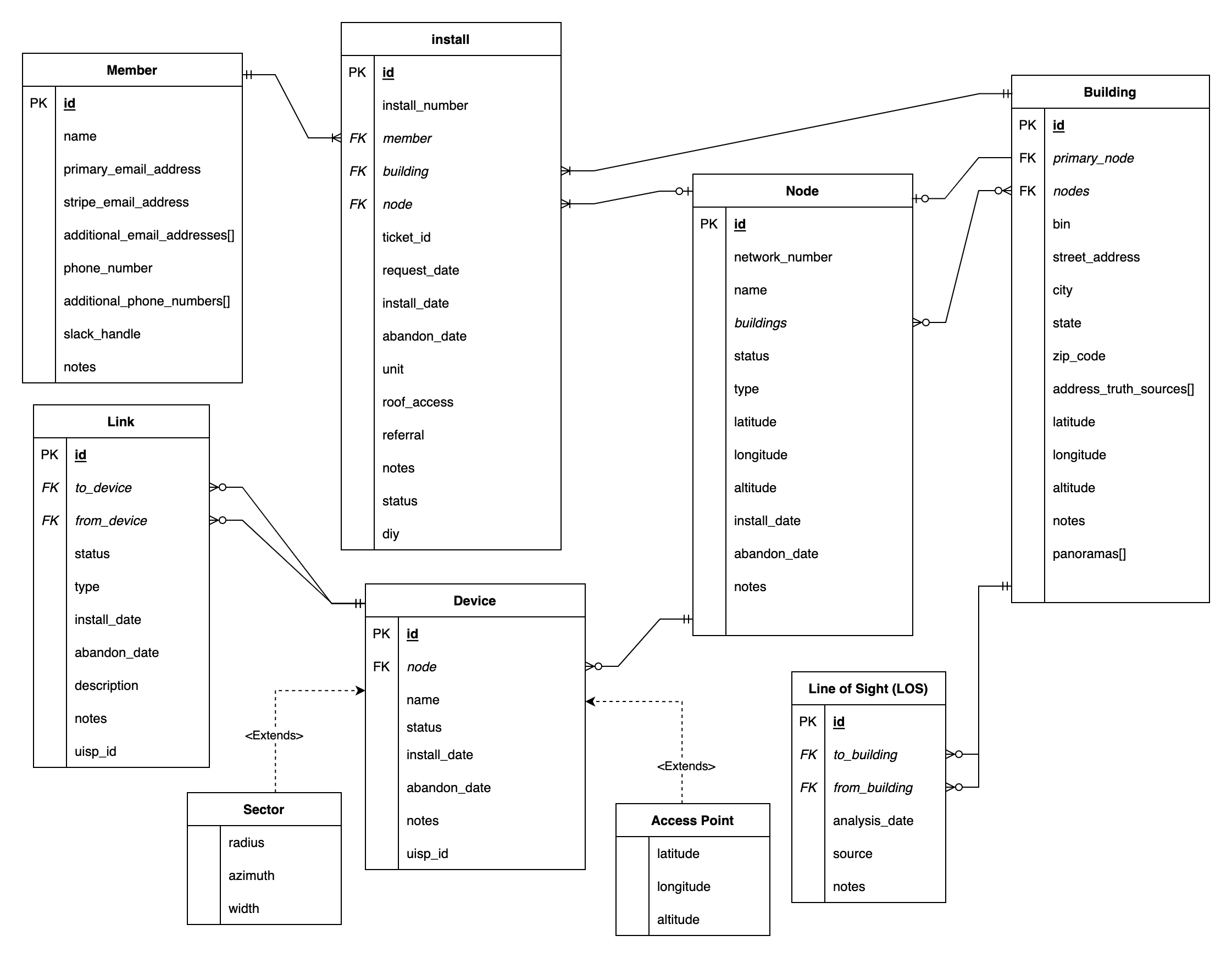
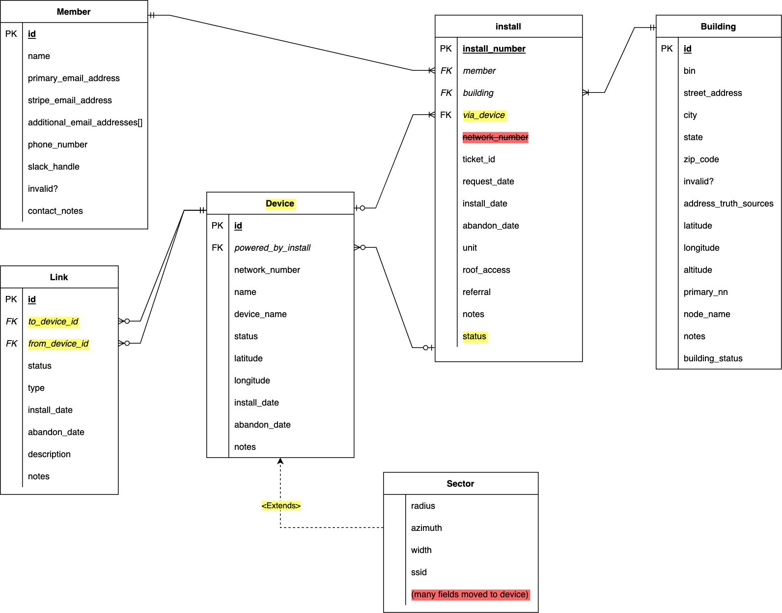
The following is a complete schema diagram, showing all fields. New additions from the current implementation are shown in yellow, and removed fields are shown in red